Hello,
I am attempting to use SPI and I just wanted to trial the transceiver option however I am not having any luck. I have tried it three ways but as you’ll see I’ve made no progress.
Firstly, utilizing the SPI sample from NCS playground I imported it all into my ncs/v1.7.1/nrf/samples/ folder and I then opened it in VSCode. I ran it and I obtained errors. Assuming that I built it incorrectly I tried running west through command line and I obtained the same two errors as shown below:
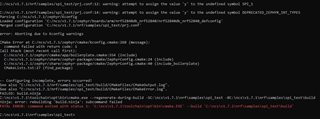
Therefore, I removed CONFIG_DEPRECATED_ZEPHYR_INT_TYPES=y and CONFIG_SPI_1=y and ran the build again, this time successfully.
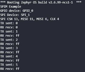
Unfortunately, the outcome wasn’t the one I was predicting, I shorted the MISO and MOSI lines to have a loop-back but on the RX line I get ff, which I assume is the initial dummy value sent? Can someone please explain why this is occurring and what can be done to remedy this, I want to read the TX that is being sent.
The code utilized is linked here: https://github.com/sigurdnev/ncs-playground/tree/master/samples/spi_test
Below is also my prj.conf before and after the changes for the build as well as the code found in main of spi_test.
#
# Copyright (c) 2020 Nordic Semiconductor ASA
#
# SPDX-License-Identifier: LicenseRef-BSD-5-Clause-Nordic
#
# CONFIG_BOARD_ENABLE_CPUNET=n
CONFIG_SPI=y
CONFIG_MAIN_STACK_SIZE=4096
# CONFIG_SPI_0=y
# UART, SPIM, and I2C are shared peripherals on nrf9160
# therefore we choose SPI3
CONFIG_SPI_1=y
CONFIG_SPI_NRFX=y
CONFIG_DEPRECATED_ZEPHYR_INT_TYPES=y
#WORKING PROJ.CONF


#
# Copyright (c) 2020 Nordic Semiconductor ASA
#
# SPDX-License-Identifier: LicenseRef-BSD-5-Clause-Nordic
#
# CONFIG_BOARD_ENABLE_CPUNET=n
CONFIG_SPI=y
CONFIG_MAIN_STACK_SIZE=4096
# CONFIG_SPI_0=y
# UART, SPIM, and I2C are shared peripherals on nrf9160
# therefore we choose SPI3

CONFIG_SPI_NRFX=y
/*
* Copyright (c) 2012-2014 Wind River Systems, Inc.
*
* SPDX-License-Identifier: Apache-2.0
*/

#include <zephyr.h>
#include <sys/printk.h>
#include <drivers/spi.h>

#define DT_DRV_COMPAT nordic_nrf_spim

struct spi_cs_control spi_cs = {
	.gpio_pin = DT_GPIO_PIN(DT_DRV_INST(0), cs_gpios),
	.gpio_dt_flags = GPIO_ACTIVE_LOW,
	.delay = 0,
};

static struct spi_config spi_cfg = {
	.operation = SPI_WORD_SET(8) | SPI_TRANSFER_MSB |
		     SPI_MODE_CPOL | SPI_MODE_CPHA,
	.frequency = 4000000,
	.slave = 0,
	.cs = &spi_cs,
};

const struct device * spi_dev;

static void spi_init(void)
{
	spi_cs.gpio_dev = device_get_binding(DT_GPIO_LABEL(DT_DRV_INST(0), cs_gpios));

	if (spi_cs.gpio_dev == NULL) {
	    printk("Could not get gpio device\n");
	} else {
		printk("GPIO device: %s\n", DT_GPIO_LABEL(DT_DRV_INST(0), cs_gpios));
	}

	spi_dev = device_get_binding(DT_LABEL(DT_DRV_INST(0)));

	if (spi_dev == NULL) {
		printk("Could not get %s device\n", DT_LABEL(DT_DRV_INST(0)));
		return;
	} else {
		printk("SPI Device: %s\n", DT_LABEL(DT_DRV_INST(0)));
		printk("SPI CSN %d, MISO %d, MOSI %d, CLK %d\n",
	       DT_GPIO_PIN(DT_DRV_INST(0), cs_gpios),
	       DT_PROP(DT_DRV_INST(0), miso_pin),
	       DT_PROP(DT_DRV_INST(0), mosi_pin),
	       DT_PROP(DT_DRV_INST(0), sck_pin));
	}
}

void spi_test_send(void)
{
	int err;
	static uint8_t tx_buffer[32];
	static uint8_t rx_buffer[32];

	const struct spi_buf tx_buf = {
		.buf = tx_buffer,
		.len = sizeof(tx_buffer)
	};
	const struct spi_buf_set tx = {
		.buffers = &tx_buf,
		.count = 1
	};

	struct spi_buf rx_buf = {
		.buf = rx_buffer,
		.len = sizeof(rx_buffer),
	};
	const struct spi_buf_set rx = {
		.buffers = &rx_buf,
		.count = 1
	};

	err = spi_transceive(spi_dev, &spi_cfg, &tx, &rx);
	if (err) {
		printk("SPI error: %d\n", err);
	} else {
		/* Connect MISO to MOSI for loopback */
		printk("TX sent: %x\n", tx_buffer[0]);
		printk("RX recv: %x\n", rx_buffer[0]);
		tx_buffer[0]++;
	}
}

void main(void)
{
	printk("SPIM Example\n");
	spi_init();
	while (1) {
		spi_test_send();
		k_sleep(K_MSEC(1000));
	}
}
Regards,
DM