Looking to permanently change UICR REGOUT0 to 5 for 3V3 on VDDOUT from dongle, to power a small Pulse Oximeter. Then using nRF Connect SDK and Zephyr, get Bluetooth GATT services and I2C(TWI) up and running.
Questions:
1. To change REGOUT0 for 3.3V using SES and nRF SDK. Do we need to connect the nRF52840 Dongle via nRF52840 DK Debug Out in order to change the UICR?
2. Can Zephyr make changes to the UICR?
3. Using nRF Connect and Zephyr. Where might there be code resetting REGOUT0 to 4 (3V)?
Any advice welcome. Many thanks, Andy
---------------------------
Following the nRF5 SDK guides > Getting Started > nRF52840 Dongle Programming Tutorial. 27 Nov 2018
https://devzone.nordicsemi.com/guides/short-range-guides/b/getting-started/posts/nrf52840-dongle-programming-tutorial Adapting firmware to set REGOUT0 properly.
⦿ Ways in which we have tried to change REGOUT0 to 5:
1_))
Guide says: “The firmware must set REGOUT0 to 3 V in order to allow it to be debugged from a DK. This is handled by the BSP if it is used with board correctly set to pca10059 by defining BOARD_PCA10059, and the firmware calls bsp_board_init().”
a. We opened ../nRF5_SDK_17.1.0_ddde560/examples/peripheral/blinky/pca10059/mbr/ses/blinky_pca10059_mbr.emProject in Segger Embedded Studio.
b(1). Edited Board Definition > boards.c line 114
from (UICR_REGOUT0_VOUT_3V0 << UICR_REGOUT0_VOUT_Pos);
to (UICR_REGOUT0_VOUT_3V3 << UICR_REGOUT0_VOUT_Pos);
b(2). We also tried editing line 108 if ((NRF_UICR->REGOUT0 & UICR_REGOUT0_VOUT_Msk) ==
from (UICR_REGOUT0_VOUT_DEFAULT << UICR_REGOUT0_VOUT_Pos))
to (UICR_REGOUT0_VOUT_3V0 << UICR_REGOUT0_VOUT_Pos))
c. In the Programmer. Plug dongle into USB port and push SW2 RESET. Add file ../nRF5_SDK_17.1.0_ddde560/examples/peripheral/blinky/pca10059/mbr/ses/Output/Release/Exe/blink_pca10059_mbr.hex
We know the code and development path works in general. If the firmware does not fall into the 'if' statement in boards.c that changes REGOUT0, then the LEDs turn on and off as expected.
Problem:
If the code NRF_NVMC->CONFIG NRF_UICR->REGOUT0 etc in the 'if' statement is hit. The nRF52840 dongle does not do anything. Subsequently, writing some firmware to read the value of REGOUT0 and getting an LED to blink that number confirms REGOUT0 is still set to 4 and VDDOUT is still at 3V
Next Step: We have a cable assembly and surface mount header on order to connect P1 on the nRF52840 Dongle (SWDIO & CLK) to nRF52840 Development kit p19 Debug Out.
2_))
Guide says: “If the BSP is not used, you should instead do the same thing directly by calling this code as early as possible in your firmware to set the REGOUT0 register if need:” Then there is a <code snippet>
a. We opened up VS Code with nRF Connect Extension v2021.12.137 and using Zephyr…
b. Create a new application from sample - zephyr/samples/basic/brinky
c. Add Build Configuration > Board nrf52840dongle_nrf52840
d. Just under: void main(void) { we added <code snippet> from Programming Tutorial.
i. Edited code snippet a bit to say if REGOUT0 = 4 then change REGOUT0 to 5 along with the required masking and bit shifting.
ii. Commented out all other code for blinking an LED.
e. Looked in file: build > zephyr > zephyr.lst
i. We see our code to change REGOUT0 to UICR_REGOUT0_VOUT_3V3
ii. Also saw #if NRF_POWER_HAS_MAINREGSTATUS looking to change NRF_UICR->REGOUT0 = UICR_REGOUT0_VOUT_3V0 which is a bit disconcerting.
f. We have also tried CONFIG_SOC_FLASH_NRF_UICR=y in pro.conf
g. In the Programmer. Plug dongle into USB port and push SW2 RESET. Add file ../blinky*/build/zephyr/zephyr.hex
Problem:
REGOUT0 is still set to 4 and VDDOUT is still at 3V
Next Step: We are to find out where there is code for the nRF52840 dongle and Zephyr with the potential to just keep overwriting REGOUT0 to 4 (3V). To see if we can change the code locally so REGOUT0 = 5. Also find out if UICR can be changed using Zephyr.
---------------------------
Notes:
nRF52840 dongle sometimes referred to as PCA10059
nRF52840 Product Specification v1.7 https://infocenter.nordicsemi.com/pdf/nRF52840_PS_v1.7.pdf
nRF52840 Dongle Hardware files https://www.nordicsemi.com/-/media/Software-and-other-downloads/Dev-Kits/nRF52840-Dongle/nRF52840-USB-Dongle---Hardware-files-2_0_0.zip
UICR User Information Configuration Registers
GATT Generic Attribute Profile
TWI Two-Wire Interface
nRF52840 Dongle Hardware files > PCA10059_Schematic_And_PCB.pdf shows L4 10μH coil between DCCH and VDD. Alludes to nRF52840 Product Specification v1.7 page 67 Figure 18: High Voltage mode DC/DC for REG0 and REG1 enabled.
Currant mA:
We are trying to get the Analog Devices / maxim integrated MAXREFDES117# Hearth-Rate and Pulse-Oximetry Monitor working. LED1 and 2 at 7mA, Pilot LED 0mA = pull of about 15mA
nRF52840 Product Specification v1.7 page 84. nRF52840 REG0 stage External current draw allowed in High voltage mode when radio output power is lower than or equal to 4dBM = 25mA.
Without any changes to:
nRF52840 Dongle - nRF6936 version 1.2.0 2020.11 We were measuring 3.3v on VDD Out with not enough current to power MAXREFDES117# properly. *However, we did get this working for a short time.
nRF52840 Dongle - nRF6829 version 2.0.0 2021.19. We are measuring 3.0v on VDD Out with not enough current to power MAXREFDES117# properly.
Noteworthy Code:
NRF_POWER->DCDCEN0 = 1;
NRF_POWER->DCDCEN = 0;
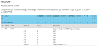
Ref table:
REGOUT0 = 4 for 3V0
REGOUT0 = 5 for 3V3
REGOUT0 = 7 for Default
IDE:
nRF Connect for Desktop.
Programmer v2.2.0
Toolchain Manager v0.10.3:
> VS Code with nRF Connect Extension v2021.12.137 using Zephyr
> Segger Embedded Studio V.5.68 with nRF5 SDK v17.1.0