Unable to force use of external 32M HFXO using S132 SDK v7.0.1

I am using v7.0.1 S132 SDK on the nRF52832 processor for BlueTooth Light coded in Segger.

I have a high speed output (50uS) to drive an external device using an internal timer (timer[3]).

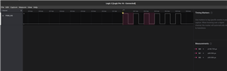
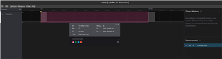
There seems to be jitter on the GPIO output.

Many posts seem to refer to forcing the use of the external 32MHz crystal using sd_clock_hfclk_request();

But querying the state using sd_clock_hfclk_is_running(p_is_running); never returns true.

I know the HF clock is running because I'm using the 16MHz clock for the timer (and using the radio to send BLE pkts).

How do I know which clock (INT or XO) is being used?

How do I force it to use the external 32MHz crystal?

Code Snippets
NOTE: The timer works but has Jitter

==============================================================================
// Main() startup calls for BLE using SDK S132 v7.0.1
	// 1) HFXO Startup fails here
	// Basic startup
    log_init();
    timers_init();  // Application timers in OS (1Hz)
    buttons_leds_init(&erase_bonds);
    power_management_init();
	// BLE Startup
    ble_stack_init();
    memset(&mac_addr, 0, sizeof(mac_addr));
    sd_ble_gap_addr_get(&mac_addr);
    gap_params_init();
    gatt_init();
    advertising_init();
    services_init();
    conn_params_init();
    peer_manager_init();
	init_my_timer();
	// 2) HFXO Startup fails here
    application_timers_start();
    advertising_start(erase_bonds);
	// 3) HFXO Startup fails here
	
==============================================================================
// Attempt to start the HFClock using HFXO
//  Fails in all 3 locations above
//  The while loop never quits ???

static uint32_t * p_is_running;
    sd_clock_hfclk_is_running(p_is_running);
    if (!p_is_running){
        //NRF_CLOCK->TASKS_HFCLKSTART = 1;

        sd_clock_hfclk_request();   // Force the use of the external HFXO?
        while (!p_is_running) 
            sd_clock_hfclk_is_running(p_is_running);
    }

==============================================================================
//  Timer init code
static const nrf_drv_timer_t m_timer3 = NRF_DRV_TIMER_INSTANCE(3);   // Internal timer[3]
nrf_drv_timer_config_t timer_cfg = NRFX_TIMER_DEFAULT_CONFIG;
void init_my_timer()
{
    timer_cfg.frequency = NRF_TIMER_FREQ_16MHz; // Use the HF Clock
    timer_cfg.bit_width = NRF_TIMER_BIT_WIDTH_32;
    err_code = nrfx_timer_init(&m_timer3, &timer_cfg, timer3_event_handler);
    APP_ERROR_CHECK(err_code);

	nrfx_timer_extended_compare(&m_timer3,
							   NRF_TIMER_CC_CHANNEL0,
							   nrf_drv_timer_us_to_ticks(&m_timer3, 50) // Init 50uS timer NOTE: This is off by about 2uS
							   NRF_TIMER_SHORT_COMPARE0_CLEAR_MASK,
							   true);

}

==============================================================================
// Note I can use buttons to start/stop this timer on the nRF52 SD
    nrfx_timer_enable(&m_timer3);   // Start the timer
    nrfx_timer_disable(&m_timer3);  // Stop the timer
	
==============================================================================
//  Timer IRQ handler
static bool timer3_trig_state = false;
static void timer3_event_handler(nrf_timer_event_t event_type, void * p_context)
{
	// Toggle PO.13 (D2) every 50uS
	if (timer3_trig_state){
		*gpio_outclr_cfg = 1UL<<ARDUINO_2_PIN;
		timer3_trig_state = false;
	} else {
		*gpio_outset_cfg = 1UL<<ARDUINO_2_PIN;
		timer3_trig_state = true;
	}
}
	

Parents
  • Hello,

    The jitter you observe is likely delays caused by higher priority Softdevice interrupts. Please see the Bluetooth Low Energy processor usage patterns  section of the Softdevice specification for more details on what kind of delays you may expect.

    Do you see the same jitter if you comment out "advertising_start()" in main()?

    But querying the state using sd_clock_hfclk_is_running(p_is_running); never returns true.

    The function will not be able to return anything in this case because the p_is_running pointer is NULL. Please try this instead:

    uint32_t is_running = 0;
    
    sd_clock_hfclk_request(); 
    
    while (!is_running) {
            sd_clock_hfclk_is_running(&is_running);
        }

    Have you considered using PWM or a combination of TIMER, PPI, and GPIOTE to simply bypass the CPU for this task?

    Minimal sample using TIMER+PPI+GPIOTE to generate clock signal out on a GPIO pin:

    https://devzone.nordicsemi.com/f/nordic-q-a/55428/nrf52840-16-mhz-clock-out-on-gpio-pin/224864#224864

    Best regards,

    Vidar

  • Thanks Vidar.

    My Bad... That resolved the issue of detecting the external clock startup.

    Unfortunately... 

    Now that I know the external clock is running , AND have switched to using the internal PWM modules...

    The jitter is much improved... BUT I still see jitter in the GPIO outputs.

    Thoughts?

    Adrian. 

  • Hi Adrian,

    How much jitter are you seeing? Does it happen on all periods, or only some?

    Maybe you can share the code so I can try to reproduce here?

    Vidar

  • Hi Vidar.

    Thankyou for your feedback, it has been very helpful.

    I am seeing very low jitter in the PWM which is less than 0.1%.

    This is good enough for us.

    BUT I need to use a timer to trigger the PWM at 100Hz

    This timer seems to have a 2% jitter on a 2MHz clock taken when the external clock is running.

    I have raised the ISR priority to 2 and it seem better (<2% jitter).

    I'm not sure if there is any other way to do that.

    Adrian.

  • Hi Adrian,

    I'm glad to hear that it accuracy has improved.

    anealca said:

    BUT I need to use a timer to trigger the PWM at 100Hz

    This timer seems to have a 2% jitter on a 2MHz clock taken when the external clock is running.

    Please correct me if I'm wrong, but I assumed you wanted this to be a continuous clock signal. If you want to start the PWM every "1/100hz" seconds to play a shorter sequence, then I would recommend you connect the timer to the PWM with PPI. The problem with using the timer interrupt to trigger the PWM task is that it will take the program several CPU cycles to enter the interrupt handler.

    Attached below is an example put together to test the accuracy here, and it seems to be OK. Please try to run this on your board to see if you  get the same result.

    Test code based on the ble_app_hrs example
    nRF5_SDK17.1.0_ble_app_hrs_pwm_test.zip

    The waveforms I captured with my logic analyzer

    Vidar

Reply
  • Hi Adrian,

    I'm glad to hear that it accuracy has improved.

    anealca said:

    BUT I need to use a timer to trigger the PWM at 100Hz

    This timer seems to have a 2% jitter on a 2MHz clock taken when the external clock is running.

    Please correct me if I'm wrong, but I assumed you wanted this to be a continuous clock signal. If you want to start the PWM every "1/100hz" seconds to play a shorter sequence, then I would recommend you connect the timer to the PWM with PPI. The problem with using the timer interrupt to trigger the PWM task is that it will take the program several CPU cycles to enter the interrupt handler.

    Attached below is an example put together to test the accuracy here, and it seems to be OK. Please try to run this on your board to see if you  get the same result.

    Test code based on the ble_app_hrs example
    nRF5_SDK17.1.0_ble_app_hrs_pwm_test.zip

    The waveforms I captured with my logic analyzer

    Vidar

Children
No Data
Related