NRF52840 dongle PWM signals with arbitrary phase-shift and duty cycle

Hi,

I am merging a PWM_driver example with a ble-peripheral-blinky example to generate PWM signals with user-defined arbitrary phase-shift and duty cycle.

I am done with the ble part that I can set arbitrary duty cycles using an android application. 

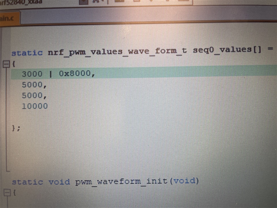
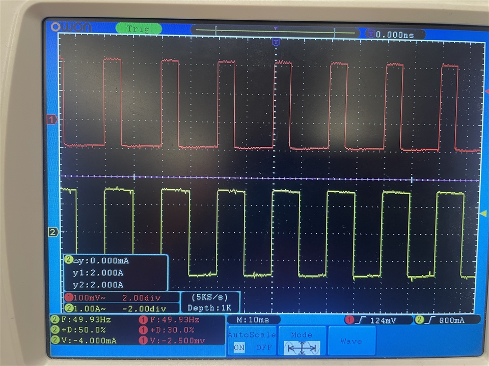
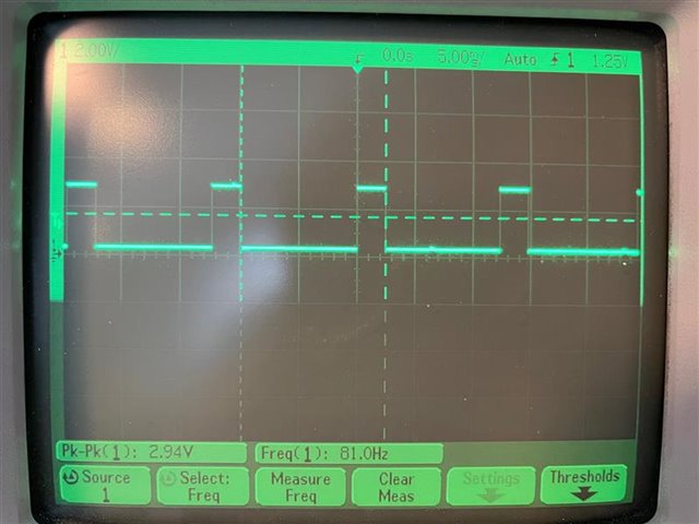
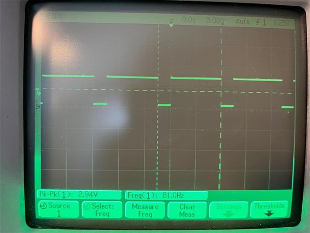
However, the problem is that no matter if I use | 0x8000 or the NRF_DRV_PWM_PIN_INVERTED flag, the polarity of my pin does not change and I cannot see any polarity change in the oscilloscope. I am using an nrf52840 dongle.

I plan two build two PWM signals that the user is able to change not only the duty cycle of that but also make an arbitrary phase-shift between the two signals.

Could you guys help me with the polarity problem?
Besides, any suggestion regarding the phase shift and how to build that would be appreciated.

Also, if there is a command to define a dead-time between the PWM signals using PWM_driver, that would be awesome.

Thanks,

Parents
  • Hi

    Could you add an image of the pwm signal you send?

    Are you able to change the duty cycle of the PWM?

    Regards,
    Sigurd Hellesvik

  • Yes, I am able to change the duty cycle. The problem is with the polarity!

    here is the my two signals that I am created for the the following commands, but as you can see, the polarity of the two signals are the same, unexpectedly!

    As you can see, the duty cycle works, but making it OR with 0x8000 will not convert the polarity of the pin!

    thanks

  • Hi

    If we have a look at the nrfx_pwm_init function, we can see that the p_configure->output_pin is only used in configure_pins:

    static void configure_pins(nrfx_pwm_t const * const p_instance,
                               nrfx_pwm_config_t const * p_config)
    {
        uint32_t out_pins[NRF_PWM_CHANNEL_COUNT];
        uint8_t i;
    
        for (i = 0; i < NRF_PWM_CHANNEL_COUNT; ++i)
        {
            uint8_t output_pin = p_config->output_pins[i];
            if (output_pin != NRFX_PWM_PIN_NOT_USED)
            {
                bool inverted = output_pin &  NRFX_PWM_PIN_INVERTED;
                out_pins[i]   = output_pin & ~NRFX_PWM_PIN_INVERTED;
    
                if (inverted)
                {
                    nrf_gpio_pin_set(out_pins[i]);
                }
                else
                {
                    nrf_gpio_pin_clear(out_pins[i]);
                }
    
                nrf_gpio_cfg_output(out_pins[i]);
            }
            else
            {
                out_pins[i] = NRF_PWM_PIN_NOT_CONNECTED;
            }
        }
    
        nrf_pwm_pins_set(p_instance->p_registers, out_pins);
    }

    It looks like NRF_DRV_PWM_PIN_INVERTED only sets the start value of the pin, and not the Polarity.

    To set the polarity, you likely need to look into nrf_pwm_sequence_t.
    From its documentation:
    " In each value, the most significant bit (15) determines the polarity of the output and the others (14-0) compose the 15-bit value to be compared with the pulse generator counter. "

    An example on how to use this sequence struct can be seen in for example demo3 in the examples/peripheral/pwm_driver.

    Are you able to set polarity using this method?

    Regards,
    Sigurd Hellesvik

  • In each value, the most significant bit (15) determines the polarity of the output and the others (14-0) compose the 15-bit value to be compared with the pulse generator counter.

    To do this, as you can see in my previous reply and the first picture, I add | 0x8000 to the sequence to change the polarity, but as is shown in the second picture the polarity is not changed! So, the Demo3, that you mentioned, does not work for changing the polarity, as it is also using the 0x8000 command. Using just 0x8000 changes the duty cycle.

    The following link shows the exact code that I am using for changing polarity and the duty cycle but it does not work for the polarity:

    https://jimmywongiot.com/2021/06/01/advanced-pulse-width-modulation-pwm-on-nordic-nrf52-series/
      

  • This reply was deleted.
Reply Children
  • Hi

    Using the nRF52840DK (PCA10056)

    I took these two measurements using the following main.c files with the pwm_driver example:

    /**
     * Copyright (c) 2015 - 2021, Nordic Semiconductor ASA
     *
     * All rights reserved.
     *
     * Redistribution and use in source and binary forms, with or without modification,
     * are permitted provided that the following conditions are met:
     *
     * 1. Redistributions of source code must retain the above copyright notice, this
     *    list of conditions and the following disclaimer.
     *
     * 2. Redistributions in binary form, except as embedded into a Nordic
     *    Semiconductor ASA integrated circuit in a product or a software update for
     *    such product, must reproduce the above copyright notice, this list of
     *    conditions and the following disclaimer in the documentation and/or other
     *    materials provided with the distribution.
     *
     * 3. Neither the name of Nordic Semiconductor ASA nor the names of its
     *    contributors may be used to endorse or promote products derived from this
     *    software without specific prior written permission.
     *
     * 4. This software, with or without modification, must only be used with a
     *    Nordic Semiconductor ASA integrated circuit.
     *
     * 5. Any software provided in binary form under this license must not be reverse
     *    engineered, decompiled, modified and/or disassembled.
     *
     * THIS SOFTWARE IS PROVIDED BY NORDIC SEMICONDUCTOR ASA "AS IS" AND ANY EXPRESS
     * OR IMPLIED WARRANTIES, INCLUDING, BUT NOT LIMITED TO, THE IMPLIED WARRANTIES
     * OF MERCHANTABILITY, NONINFRINGEMENT, AND FITNESS FOR A PARTICULAR PURPOSE ARE
     * DISCLAIMED. IN NO EVENT SHALL NORDIC SEMICONDUCTOR ASA OR CONTRIBUTORS BE
     * LIABLE FOR ANY DIRECT, INDIRECT, INCIDENTAL, SPECIAL, EXEMPLARY, OR
     * CONSEQUENTIAL DAMAGES (INCLUDING, BUT NOT LIMITED TO, PROCUREMENT OF SUBSTITUTE
     * GOODS OR SERVICES; LOSS OF USE, DATA, OR PROFITS; OR BUSINESS INTERRUPTION)
     * HOWEVER CAUSED AND ON ANY THEORY OF LIABILITY, WHETHER IN CONTRACT, STRICT
     * LIABILITY, OR TORT (INCLUDING NEGLIGENCE OR OTHERWISE) ARISING IN ANY WAY OUT
     * OF THE USE OF THIS SOFTWARE, EVEN IF ADVISED OF THE POSSIBILITY OF SUCH DAMAGE.
     *
     */
    /** @file
     * @defgroup pwm_example_main main.c
     * @{
     * @ingroup pwm_example
     *
     * @brief PWM Example Application main file.
     *
     * This file contains the source code for a sample application using PWM.
     */
    
    #include <stdio.h>
    #include <string.h>
    #include "nrf_drv_pwm.h"
    #include "app_util_platform.h"
    #include "app_error.h"
    #include "boards.h"
    #include "bsp.h"
    #include "app_timer.h"
    #include "nrf_drv_clock.h"
    
    #include "nrf_log.h"
    #include "nrf_log_ctrl.h"
    #include "nrf_log_default_backends.h"
    
    static nrf_drv_pwm_t m_pwm0 = NRF_DRV_PWM_INSTANCE(0);
    static nrf_drv_pwm_t m_pwm1 = NRF_DRV_PWM_INSTANCE(1);
    static nrf_drv_pwm_t m_pwm2 = NRF_DRV_PWM_INSTANCE(2);
    
    // This is for tracking PWM instances being used, so we can unintialize only
    // the relevant ones when switching from one demo to another.
    #define USED_PWM(idx) (1UL << idx)
    static uint8_t m_used = 0;
    
    
    static uint16_t const              m_demo1_top  = 1000;
    static uint16_t const              m_demo1_step = 1;
    static uint8_t                     m_demo1_phase;
    static nrf_pwm_values_individual_t m_demo1_seq_values;
    static nrf_pwm_sequence_t const    m_demo1_seq =
    {
        .values.p_individual = &m_demo1_seq_values,
        .length              = NRF_PWM_VALUES_LENGTH(m_demo1_seq_values),
        .repeats             = 0,
        .end_delay           = 0
    };
    
    static void demo1_handler(nrf_drv_pwm_evt_type_t event_type)
    {
    
        if (event_type == NRF_DRV_PWM_EVT_FINISHED)
        {
            uint8_t channel    = m_demo1_phase >> 1;
            bool    down       = m_demo1_phase & 1;
            bool    next_phase = false;
    
            uint16_t * p_channels = (uint16_t *)&m_demo1_seq_values;
            uint16_t value = p_channels[channel];
            if (down)
            {
              next_phase = true;
                value =0;
                if (value == 0)
                {
                    next_phase = true;
                }
                
            }
            else
            {
                value += m_demo1_step;
                if (value >= m_demo1_top)
                {
                    next_phase = true;
                }
                
            }
            p_channels[channel] = value;
    
            if (next_phase)
            {
                if (++m_demo1_phase >= 2 * NRF_PWM_CHANNEL_COUNT)
                {
                    m_demo1_phase = 0;
                }
            }
        }
        
    }
    static void demo1(void)
    {
        NRF_LOG_INFO("Demo 1");
    
        /*
         * This demo plays back a sequence with different values for individual
         * channels (LED 1 - LED 4). Only four values are used (one per channel).
         * Every time the values are loaded into the compare registers, they are
         * updated in the provided event handler. The values are updated in such
         * a way that increase and decrease of the light intensity can be observed
         * continuously on succeeding channels (one second per channel).
         */
    
        nrf_drv_pwm_config_t const config0 =
        {
            .output_pins =
            {
                BSP_LED_0, // channel 0
                BSP_LED_1 + 0x8000, // channel 1
                BSP_LED_3 | NRF_DRV_PWM_PIN_INVERTED, // channel 2
                BSP_LED_2 | NRF_DRV_PWM_PIN_INVERTED  // channel 3
            },
            .irq_priority = APP_IRQ_PRIORITY_LOWEST,
            .base_clock   = NRF_PWM_CLK_1MHz,
            .count_mode   = NRF_PWM_MODE_UP,
            .top_value    = m_demo1_top,
            .load_mode    = NRF_PWM_LOAD_INDIVIDUAL,
            .step_mode    = NRF_PWM_STEP_AUTO
        };
        APP_ERROR_CHECK(nrf_drv_pwm_init(&m_pwm0, &config0, demo1_handler));
        m_used |= USED_PWM(0);
    
        m_demo1_seq_values.channel_0 = 0;
        m_demo1_seq_values.channel_1 = 0;
        m_demo1_seq_values.channel_2 = 0;
        m_demo1_seq_values.channel_3 = 0;
        m_demo1_phase                = 0;
    
        (void)nrf_drv_pwm_simple_playback(&m_pwm0, &m_demo1_seq, 1,
                                          NRF_DRV_PWM_FLAG_LOOP);
    }
    
    
    static void demo2(void)
    {
        NRF_LOG_INFO("Demo 2");
    
        /*
         * This demo plays back two concatenated sequences:
         * - Sequence 0: Light intensity is increased in 25 steps during one second.
         * - Sequence 1: LED blinks twice (100 ms off, 100 ms on), then stays off
         *   for 200 ms.
         * The same output is generated on all 4 channels (LED 1 - LED 4).
         * The playback is repeated in a loop.
         */
    
        enum { // [local constants]
            TOP        = 10000,
            STEP_COUNT = 25
        };
    
        nrf_drv_pwm_config_t const config0 =
        {
            .output_pins =
            {
                BSP_LED_0 | NRF_DRV_PWM_PIN_INVERTED, // channel 0
                BSP_LED_1 | NRF_DRV_PWM_PIN_INVERTED, // channel 1
                BSP_LED_2 | NRF_DRV_PWM_PIN_INVERTED, // channel 2
                BSP_LED_3 | NRF_DRV_PWM_PIN_INVERTED  // channel 3
            },
            .irq_priority = APP_IRQ_PRIORITY_LOWEST,
            .base_clock   = NRF_PWM_CLK_500kHz,
            .count_mode   = NRF_PWM_MODE_UP,
            .top_value    = TOP,
            .load_mode    = NRF_PWM_LOAD_COMMON,
            .step_mode    = NRF_PWM_STEP_AUTO
        };
        APP_ERROR_CHECK(nrf_drv_pwm_init(&m_pwm0, &config0, NULL));
        m_used |= USED_PWM(0);
    
        // This array cannot be allocated on stack (hence "static") and it must
        // be in RAM.
        static nrf_pwm_values_common_t seq0_values[STEP_COUNT];
        uint16_t value = 0;
        uint16_t step  = TOP / STEP_COUNT;
        uint8_t  i;
        for (i = 0; i < STEP_COUNT; ++i)
        {
            value         += step;
            seq0_values[i] = value;
        }
        nrf_pwm_sequence_t const seq0 =
        {
            .values.p_raw = seq0_values,
            .length          = NRF_PWM_VALUES_LENGTH(seq0_values),
            .repeats         = 1,
            .end_delay       = 0
        };
    
        // This array cannot be allocated on stack (hence "static") and it must
        // be in RAM (hence no "const", though its content is not changed).
        static nrf_pwm_values_common_t /*const*/ seq1_values[] =
        {
                 0,
            0x8000,
                 0,
            0x8000,
                 0,
                 0
        };
        static nrf_pwm_sequence_t const seq1 =
        {
            .values.p_common = seq1_values,
            .length          = NRF_PWM_VALUES_LENGTH(seq1_values),
            .repeats         = 4,
            .end_delay       = 0
        };
    
        (void)nrf_drv_pwm_complex_playback(&m_pwm0, &seq0, &seq1, 1,
                                           NRF_DRV_PWM_FLAG_LOOP);
    }
    
    
    static void demo3(void)
    {
        NRF_LOG_INFO("Demo 3");
    
        /*
         * This demo uses only one channel, which is reflected on LED 1.
         * The LED blinks three times (200 ms on, 200 ms off), then it stays off
         * for one second.
         * This scheme is performed three times before the peripheral is stopped.
         */
    
        nrf_drv_pwm_config_t const config0 =
        {
            .output_pins =
            {
                BSP_LED_0 | NRF_DRV_PWM_PIN_INVERTED, // channel 0
                NRF_DRV_PWM_PIN_NOT_USED,             // channel 1
                NRF_DRV_PWM_PIN_NOT_USED,             // channel 2
                NRF_DRV_PWM_PIN_NOT_USED,             // channel 3
            },
            .irq_priority = APP_IRQ_PRIORITY_LOWEST,
            .base_clock   = NRF_PWM_CLK_2MHz,
            .count_mode   = NRF_PWM_MODE_UP,
            .top_value    = 25000,
            .load_mode    = NRF_PWM_LOAD_COMMON,
            .step_mode    = NRF_PWM_STEP_AUTO
        };
        APP_ERROR_CHECK(nrf_drv_pwm_init(&m_pwm0, &config0, NULL));
        m_used |= USED_PWM(0);
    
        // This array cannot be allocated on stack (hence "static") and it must
        // be in RAM (hence no "const", though its content is not changed).
        static uint16_t /*const*/ seq_values[] =
        {
            20000
        };
        nrf_pwm_sequence_t const seq =
        {
            .values.p_common = seq_values,
            .length          = NRF_PWM_VALUES_LENGTH(seq_values),
            .repeats         = 0,
            .end_delay       = 0
        };
    
        (void)nrf_drv_pwm_simple_playback(&m_pwm0, &seq, 0, NRF_DRV_PWM_FLAG_STOP);
    }
    
    
    static void demo4(void)
    {
        NRF_LOG_INFO("Demo 4");
    
        /*
         * This demo uses all three PWM peripheral instances:
         * - PWM0 drives LED 1 and LED 2: Subsequent 2-bit binary values are
         *   presented every 500 ms.
         * - PWM1 drives LED 3: During 500 ms, the LED increases and decreases
         *   the light intensity, then it stays off for 1500 ms.
         * - PWM2 drives LED 4: For 500 ms, the LED stays off, then during 1500 ms
         *   it increases and decreases the light intensity.
         * Simple playback with grouped loading mode is used for PWM0, and complex
         * playback with common loading mode is used for both PWM1 and PWM2.
         */
    
        nrf_drv_pwm_config_t config =
        {
            // These are the common configuration options we use for all PWM
            // instances.
            .irq_priority = APP_IRQ_PRIORITY_LOWEST,
            .count_mode   = NRF_PWM_MODE_UP,
            .step_mode    = NRF_PWM_STEP_AUTO,
        };
    
        ////////////////////////////////////////////////////////////////////////////
        // PWM0 initialization.
    
        config.output_pins[0] = BSP_LED_0 | NRF_DRV_PWM_PIN_INVERTED;
        config.output_pins[1] = NRF_DRV_PWM_PIN_NOT_USED;
        config.output_pins[2] = BSP_LED_1 | NRF_DRV_PWM_PIN_INVERTED;
        config.output_pins[3] = NRF_DRV_PWM_PIN_NOT_USED;
        config.base_clock     = NRF_PWM_CLK_125kHz;
        config.top_value      = 31250; // 250ms period
        config.load_mode      = NRF_PWM_LOAD_GROUPED;
        APP_ERROR_CHECK(nrf_drv_pwm_init(&m_pwm0, &config, NULL));
        m_used |= USED_PWM(0);
    
        // This array cannot be allocated on stack (hence "static") and it must
        // be in RAM (hence no "const", though its content is not changed).
        static nrf_pwm_values_grouped_t /*const*/ pwm0_seq_values[] =
        {
            {      0,      0 },
            { 0x8000,      0 },
            {      0, 0x8000 },
            { 0x8000, 0x8000 }
        };
        nrf_pwm_sequence_t const pwm0_seq =
        {
            .values.p_grouped = pwm0_seq_values,
            .length           = NRF_PWM_VALUES_LENGTH(pwm0_seq_values),
            .repeats          = 1,
            .end_delay        = 0
        };
    
        ////////////////////////////////////////////////////////////////////////////
        // Common settings for PWM1 and PWM2.
    
        enum { // [local constants]
            TOP        = 5000,
            STEP_COUNT = 50
        };
    
        config.base_clock = NRF_PWM_CLK_1MHz;
        config.top_value  = TOP;
        config.load_mode  = NRF_PWM_LOAD_COMMON;
    
        // This array cannot be allocated on stack (hence "static") and it must
        // be in RAM.
        static nrf_pwm_values_common_t fade_in_out_values[2 * STEP_COUNT];
        uint16_t value = 0;
        uint16_t step  = TOP / STEP_COUNT;
        uint8_t  i;
        for (i = 0; i < STEP_COUNT; ++i)
        {
            value                             += step;
            fade_in_out_values[i]              = value;
            fade_in_out_values[STEP_COUNT + i] = TOP - value;
        }
    
        // This array cannot be allocated on stack (hence "static") and it must
        // be in RAM (hence no "const", though its content is not changed).
        static nrf_pwm_values_common_t /*const*/ stay_off_values[2] = { 0, 0 };
    
        ////////////////////////////////////////////////////////////////////////////
        // PWM1 initialization.
    
        config.output_pins[0] = NRF_DRV_PWM_PIN_NOT_USED;
        config.output_pins[1] = NRF_DRV_PWM_PIN_NOT_USED;
        config.output_pins[2] = BSP_LED_2 | NRF_DRV_PWM_PIN_INVERTED;
        config.output_pins[3] = NRF_DRV_PWM_PIN_NOT_USED;
        APP_ERROR_CHECK(nrf_drv_pwm_init(&m_pwm1, &config, NULL));
        m_used |= USED_PWM(1);
    
        // Sequence 0 - fade-in/fade-out, duration: 500 ms.
        nrf_pwm_sequence_t const pwm1_seq0 =
        {
            .values.p_common = fade_in_out_values,
            .length          = NRF_PWM_VALUES_LENGTH(fade_in_out_values),
            .repeats         = 0,
            .end_delay       = 0
        };
        // Sequence 1 - off, duration: 1500 ms.
        nrf_pwm_sequence_t const pwm1_seq1 =
        {
            .values.p_common = stay_off_values,
            .length          = 2,
            .repeats         = 149,
            .end_delay       = 0
        };
    
        ////////////////////////////////////////////////////////////////////////////
        // PWM2 initialization.
    
        config.output_pins[0] = NRF_DRV_PWM_PIN_NOT_USED;
        config.output_pins[1] = NRF_DRV_PWM_PIN_NOT_USED;
        config.output_pins[2] = NRF_DRV_PWM_PIN_NOT_USED;
        config.output_pins[3] = BSP_LED_3 | NRF_DRV_PWM_PIN_INVERTED;
        APP_ERROR_CHECK(nrf_drv_pwm_init(&m_pwm2, &config, NULL));
        m_used |= USED_PWM(2);
    
        // Sequence 0 - fade-in/fade-out, duration: 1500 ms.
        nrf_pwm_sequence_t const pwm2_seq0 =
        {
            .values.p_common = stay_off_values,
            .length          = 2,
            .repeats         = 49,
            .end_delay       = 0
        };
        // Sequence 1 - off, duration: 500 ms.
        nrf_pwm_sequence_t const pwm2_seq1 =
        {
            .values.p_common = fade_in_out_values,
            .length          = NRF_PWM_VALUES_LENGTH(fade_in_out_values),
            .repeats         = 2,
            .end_delay       = 0
        };
    
        (void)nrf_drv_pwm_simple_playback(&m_pwm0, &pwm0_seq, 1,
                                          NRF_DRV_PWM_FLAG_LOOP);
        (void)nrf_drv_pwm_complex_playback(&m_pwm1, &pwm1_seq0, &pwm1_seq1, 1,
                                           NRF_DRV_PWM_FLAG_LOOP);
        (void)nrf_drv_pwm_complex_playback(&m_pwm2, &pwm2_seq0, &pwm2_seq1, 1,
                                           NRF_DRV_PWM_FLAG_LOOP);
    }
    
    
    static void demo5(void)
    {
        NRF_LOG_INFO("Demo 5");
    
        /*
         * This demo, similarly to demo1, plays back a sequence with different
         * values for individual channels. Unlike demo 1, however, it does not use
         * an event handler. Therefore, the PWM peripheral does not use interrupts
         * and the CPU can stay in sleep mode.
         * The LEDs (1-4) blink separately. They are turned on for 125 ms each,
         * in counterclockwise order (looking at the board).
         */
    
        nrf_drv_pwm_config_t const config0 =
        {
            .output_pins =
            {
                BSP_LED_0 | NRF_DRV_PWM_PIN_INVERTED, // channel 0
                BSP_LED_2 | NRF_DRV_PWM_PIN_INVERTED, // channel 1
                BSP_LED_3 | NRF_DRV_PWM_PIN_INVERTED, // channel 2
                BSP_LED_1 | NRF_DRV_PWM_PIN_INVERTED  // channel 3
            },
            .irq_priority = APP_IRQ_PRIORITY_LOWEST,
            .base_clock   = NRF_PWM_CLK_125kHz,
            .count_mode   = NRF_PWM_MODE_UP,
            .top_value    = 15625,
            .load_mode    = NRF_PWM_LOAD_INDIVIDUAL,
            .step_mode    = NRF_PWM_STEP_AUTO
        };
        APP_ERROR_CHECK(nrf_drv_pwm_init(&m_pwm0, &config0, NULL));
        m_used |= USED_PWM(0);
    
        // This array cannot be allocated on stack (hence "static") and it must
        // be in RAM (hence no "const", though its content is not changed).
        static nrf_pwm_values_individual_t /*const*/ seq_values[] =
        {
            { 0x8000,      0,      0,      0 },
            {      0, 0x8000,      0,      0 },
            {      0,      0, 0x8000,      0 },
            {      0,      0,      0, 0x8000 }
        };
        nrf_pwm_sequence_t const seq =
        {
            .values.p_individual = seq_values,
            .length              = NRF_PWM_VALUES_LENGTH(seq_values),
            .repeats             = 0,
            .end_delay           = 0
        };
    
        (void)nrf_drv_pwm_simple_playback(&m_pwm0, &seq, 1, NRF_DRV_PWM_FLAG_LOOP);
    }
    
    
    static void bsp_evt_handler(bsp_event_t evt)
    {
        void (* const demos[])(void) =
        {
            demo1,
            demo2,
            demo3,
            demo4,
            demo5
        };
        uint8_t const  demo_idx_max = (sizeof(demos) / sizeof(demos[0])) - 1;
        static uint8_t demo_idx     = 0;
    
        switch (evt)
        {
            // Button 1 - switch to the previous demo.
            case BSP_EVENT_KEY_0:
                if (demo_idx > 0)
                {
                    --demo_idx;
                }
                else
                {
                    demo_idx = demo_idx_max;
                }
                break;
    
            // Button 2 - switch to the next demo.
            case BSP_EVENT_KEY_1:
                if (demo_idx < demo_idx_max)
                {
                    ++demo_idx;
                }
                else
                {
                    demo_idx = 0;
                }
                break;
    
            default:
                return;
        }
    
        if (m_used & USED_PWM(0))
        {
            nrf_drv_pwm_uninit(&m_pwm0);
        }
        if (m_used & USED_PWM(1))
        {
            nrf_drv_pwm_uninit(&m_pwm1);
        }
        if (m_used & USED_PWM(2))
        {
            nrf_drv_pwm_uninit(&m_pwm2);
        }
        m_used = 0;
    
        demos[demo_idx]();
    }
    static void init_bsp()
    {
        APP_ERROR_CHECK(nrf_drv_clock_init());
        nrf_drv_clock_lfclk_request(NULL);
    
        APP_ERROR_CHECK(app_timer_init());
        APP_ERROR_CHECK(bsp_init(BSP_INIT_BUTTONS, bsp_evt_handler));
        APP_ERROR_CHECK(bsp_buttons_enable());
    }
    
    
    void app_error_fault_handler(uint32_t id, uint32_t pc, uint32_t info)
    {
        bsp_board_leds_on();
        app_error_save_and_stop(id, pc, info);
    }
    
    
    int main(void)
    {
        APP_ERROR_CHECK(NRF_LOG_INIT(NULL));
        NRF_LOG_DEFAULT_BACKENDS_INIT();
    
        init_bsp();
    
        NRF_LOG_INFO("PWM example started.");
    
        // Start with Demo 1, then switch to another one when the user presses
        // button 1 or button 2 (see the 'bsp_evt_handler' function).
        demo3();
    
        for (;;)
        {
            // Wait for an event.
            __WFE();
    
            // Clear the event register.
            __SEV();
            __WFE();
    
            NRF_LOG_FLUSH();
        }
    }
    
    
    /** @} */
    

    8540.pwm_not_inverted.hex

    /**
     * Copyright (c) 2015 - 2021, Nordic Semiconductor ASA
     *
     * All rights reserved.
     *
     * Redistribution and use in source and binary forms, with or without modification,
     * are permitted provided that the following conditions are met:
     *
     * 1. Redistributions of source code must retain the above copyright notice, this
     *    list of conditions and the following disclaimer.
     *
     * 2. Redistributions in binary form, except as embedded into a Nordic
     *    Semiconductor ASA integrated circuit in a product or a software update for
     *    such product, must reproduce the above copyright notice, this list of
     *    conditions and the following disclaimer in the documentation and/or other
     *    materials provided with the distribution.
     *
     * 3. Neither the name of Nordic Semiconductor ASA nor the names of its
     *    contributors may be used to endorse or promote products derived from this
     *    software without specific prior written permission.
     *
     * 4. This software, with or without modification, must only be used with a
     *    Nordic Semiconductor ASA integrated circuit.
     *
     * 5. Any software provided in binary form under this license must not be reverse
     *    engineered, decompiled, modified and/or disassembled.
     *
     * THIS SOFTWARE IS PROVIDED BY NORDIC SEMICONDUCTOR ASA "AS IS" AND ANY EXPRESS
     * OR IMPLIED WARRANTIES, INCLUDING, BUT NOT LIMITED TO, THE IMPLIED WARRANTIES
     * OF MERCHANTABILITY, NONINFRINGEMENT, AND FITNESS FOR A PARTICULAR PURPOSE ARE
     * DISCLAIMED. IN NO EVENT SHALL NORDIC SEMICONDUCTOR ASA OR CONTRIBUTORS BE
     * LIABLE FOR ANY DIRECT, INDIRECT, INCIDENTAL, SPECIAL, EXEMPLARY, OR
     * CONSEQUENTIAL DAMAGES (INCLUDING, BUT NOT LIMITED TO, PROCUREMENT OF SUBSTITUTE
     * GOODS OR SERVICES; LOSS OF USE, DATA, OR PROFITS; OR BUSINESS INTERRUPTION)
     * HOWEVER CAUSED AND ON ANY THEORY OF LIABILITY, WHETHER IN CONTRACT, STRICT
     * LIABILITY, OR TORT (INCLUDING NEGLIGENCE OR OTHERWISE) ARISING IN ANY WAY OUT
     * OF THE USE OF THIS SOFTWARE, EVEN IF ADVISED OF THE POSSIBILITY OF SUCH DAMAGE.
     *
     */
    /** @file
     * @defgroup pwm_example_main main.c
     * @{
     * @ingroup pwm_example
     *
     * @brief PWM Example Application main file.
     *
     * This file contains the source code for a sample application using PWM.
     */
    
    #include <stdio.h>
    #include <string.h>
    #include "nrf_drv_pwm.h"
    #include "app_util_platform.h"
    #include "app_error.h"
    #include "boards.h"
    #include "bsp.h"
    #include "app_timer.h"
    #include "nrf_drv_clock.h"
    
    #include "nrf_log.h"
    #include "nrf_log_ctrl.h"
    #include "nrf_log_default_backends.h"
    
    static nrf_drv_pwm_t m_pwm0 = NRF_DRV_PWM_INSTANCE(0);
    static nrf_drv_pwm_t m_pwm1 = NRF_DRV_PWM_INSTANCE(1);
    static nrf_drv_pwm_t m_pwm2 = NRF_DRV_PWM_INSTANCE(2);
    
    // This is for tracking PWM instances being used, so we can unintialize only
    // the relevant ones when switching from one demo to another.
    #define USED_PWM(idx) (1UL << idx)
    static uint8_t m_used = 0;
    
    
    static uint16_t const              m_demo1_top  = 1000;
    static uint16_t const              m_demo1_step = 1;
    static uint8_t                     m_demo1_phase;
    static nrf_pwm_values_individual_t m_demo1_seq_values;
    static nrf_pwm_sequence_t const    m_demo1_seq =
    {
        .values.p_individual = &m_demo1_seq_values,
        .length              = NRF_PWM_VALUES_LENGTH(m_demo1_seq_values),
        .repeats             = 0,
        .end_delay           = 0
    };
    
    static void demo1_handler(nrf_drv_pwm_evt_type_t event_type)
    {
    
        if (event_type == NRF_DRV_PWM_EVT_FINISHED)
        {
            uint8_t channel    = m_demo1_phase >> 1;
            bool    down       = m_demo1_phase & 1;
            bool    next_phase = false;
    
            uint16_t * p_channels = (uint16_t *)&m_demo1_seq_values;
            uint16_t value = p_channels[channel];
            if (down)
            {
              next_phase = true;
                value =0;
                if (value == 0)
                {
                    next_phase = true;
                }
                
            }
            else
            {
                value += m_demo1_step;
                if (value >= m_demo1_top)
                {
                    next_phase = true;
                }
                
            }
            p_channels[channel] = value;
    
            if (next_phase)
            {
                if (++m_demo1_phase >= 2 * NRF_PWM_CHANNEL_COUNT)
                {
                    m_demo1_phase = 0;
                }
            }
        }
        
    }
    static void demo1(void)
    {
        NRF_LOG_INFO("Demo 1");
    
        /*
         * This demo plays back a sequence with different values for individual
         * channels (LED 1 - LED 4). Only four values are used (one per channel).
         * Every time the values are loaded into the compare registers, they are
         * updated in the provided event handler. The values are updated in such
         * a way that increase and decrease of the light intensity can be observed
         * continuously on succeeding channels (one second per channel).
         */
    
        nrf_drv_pwm_config_t const config0 =
        {
            .output_pins =
            {
                BSP_LED_0, // channel 0
                BSP_LED_1 + 0x8000, // channel 1
                BSP_LED_3 | NRF_DRV_PWM_PIN_INVERTED, // channel 2
                BSP_LED_2 | NRF_DRV_PWM_PIN_INVERTED  // channel 3
            },
            .irq_priority = APP_IRQ_PRIORITY_LOWEST,
            .base_clock   = NRF_PWM_CLK_1MHz,
            .count_mode   = NRF_PWM_MODE_UP,
            .top_value    = m_demo1_top,
            .load_mode    = NRF_PWM_LOAD_INDIVIDUAL,
            .step_mode    = NRF_PWM_STEP_AUTO
        };
        APP_ERROR_CHECK(nrf_drv_pwm_init(&m_pwm0, &config0, demo1_handler));
        m_used |= USED_PWM(0);
    
        m_demo1_seq_values.channel_0 = 0;
        m_demo1_seq_values.channel_1 = 0;
        m_demo1_seq_values.channel_2 = 0;
        m_demo1_seq_values.channel_3 = 0;
        m_demo1_phase                = 0;
    
        (void)nrf_drv_pwm_simple_playback(&m_pwm0, &m_demo1_seq, 1,
                                          NRF_DRV_PWM_FLAG_LOOP);
    }
    
    
    static void demo2(void)
    {
        NRF_LOG_INFO("Demo 2");
    
        /*
         * This demo plays back two concatenated sequences:
         * - Sequence 0: Light intensity is increased in 25 steps during one second.
         * - Sequence 1: LED blinks twice (100 ms off, 100 ms on), then stays off
         *   for 200 ms.
         * The same output is generated on all 4 channels (LED 1 - LED 4).
         * The playback is repeated in a loop.
         */
    
        enum { // [local constants]
            TOP        = 10000,
            STEP_COUNT = 25
        };
    
        nrf_drv_pwm_config_t const config0 =
        {
            .output_pins =
            {
                BSP_LED_0 | NRF_DRV_PWM_PIN_INVERTED, // channel 0
                BSP_LED_1 | NRF_DRV_PWM_PIN_INVERTED, // channel 1
                BSP_LED_2 | NRF_DRV_PWM_PIN_INVERTED, // channel 2
                BSP_LED_3 | NRF_DRV_PWM_PIN_INVERTED  // channel 3
            },
            .irq_priority = APP_IRQ_PRIORITY_LOWEST,
            .base_clock   = NRF_PWM_CLK_500kHz,
            .count_mode   = NRF_PWM_MODE_UP,
            .top_value    = TOP,
            .load_mode    = NRF_PWM_LOAD_COMMON,
            .step_mode    = NRF_PWM_STEP_AUTO
        };
        APP_ERROR_CHECK(nrf_drv_pwm_init(&m_pwm0, &config0, NULL));
        m_used |= USED_PWM(0);
    
        // This array cannot be allocated on stack (hence "static") and it must
        // be in RAM.
        static nrf_pwm_values_common_t seq0_values[STEP_COUNT];
        uint16_t value = 0;
        uint16_t step  = TOP / STEP_COUNT;
        uint8_t  i;
        for (i = 0; i < STEP_COUNT; ++i)
        {
            value         += step;
            seq0_values[i] = value;
        }
        nrf_pwm_sequence_t const seq0 =
        {
            .values.p_raw = seq0_values,
            .length          = NRF_PWM_VALUES_LENGTH(seq0_values),
            .repeats         = 1,
            .end_delay       = 0
        };
    
        // This array cannot be allocated on stack (hence "static") and it must
        // be in RAM (hence no "const", though its content is not changed).
        static nrf_pwm_values_common_t /*const*/ seq1_values[] =
        {
                 0,
            0x8000,
                 0,
            0x8000,
                 0,
                 0
        };
        static nrf_pwm_sequence_t const seq1 =
        {
            .values.p_common = seq1_values,
            .length          = NRF_PWM_VALUES_LENGTH(seq1_values),
            .repeats         = 4,
            .end_delay       = 0
        };
    
        (void)nrf_drv_pwm_complex_playback(&m_pwm0, &seq0, &seq1, 1,
                                           NRF_DRV_PWM_FLAG_LOOP);
    }
    
    
    static void demo3(void)
    {
        NRF_LOG_INFO("Demo 3");
    
        /*
         * This demo uses only one channel, which is reflected on LED 1.
         * The LED blinks three times (200 ms on, 200 ms off), then it stays off
         * for one second.
         * This scheme is performed three times before the peripheral is stopped.
         */
    
        nrf_drv_pwm_config_t const config0 =
        {
            .output_pins =
            {
                BSP_LED_0 | NRF_DRV_PWM_PIN_INVERTED, // channel 0
                NRF_DRV_PWM_PIN_NOT_USED,             // channel 1
                NRF_DRV_PWM_PIN_NOT_USED,             // channel 2
                NRF_DRV_PWM_PIN_NOT_USED,             // channel 3
            },
            .irq_priority = APP_IRQ_PRIORITY_LOWEST,
            .base_clock   = NRF_PWM_CLK_2MHz,
            .count_mode   = NRF_PWM_MODE_UP,
            .top_value    = 25000,
            .load_mode    = NRF_PWM_LOAD_COMMON,
            .step_mode    = NRF_PWM_STEP_AUTO
        };
        APP_ERROR_CHECK(nrf_drv_pwm_init(&m_pwm0, &config0, NULL));
        m_used |= USED_PWM(0);
    
        // This array cannot be allocated on stack (hence "static") and it must
        // be in RAM (hence no "const", though its content is not changed).
        static uint16_t /*const*/ seq_values[] =
        {
            20000 | 0x8000
        };
        nrf_pwm_sequence_t const seq =
        {
            .values.p_common = seq_values,
            .length          = NRF_PWM_VALUES_LENGTH(seq_values),
            .repeats         = 0,
            .end_delay       = 0
        };
    
        (void)nrf_drv_pwm_simple_playback(&m_pwm0, &seq, 0, NRF_DRV_PWM_FLAG_STOP);
    }
    
    
    static void demo4(void)
    {
        NRF_LOG_INFO("Demo 4");
    
        /*
         * This demo uses all three PWM peripheral instances:
         * - PWM0 drives LED 1 and LED 2: Subsequent 2-bit binary values are
         *   presented every 500 ms.
         * - PWM1 drives LED 3: During 500 ms, the LED increases and decreases
         *   the light intensity, then it stays off for 1500 ms.
         * - PWM2 drives LED 4: For 500 ms, the LED stays off, then during 1500 ms
         *   it increases and decreases the light intensity.
         * Simple playback with grouped loading mode is used for PWM0, and complex
         * playback with common loading mode is used for both PWM1 and PWM2.
         */
    
        nrf_drv_pwm_config_t config =
        {
            // These are the common configuration options we use for all PWM
            // instances.
            .irq_priority = APP_IRQ_PRIORITY_LOWEST,
            .count_mode   = NRF_PWM_MODE_UP,
            .step_mode    = NRF_PWM_STEP_AUTO,
        };
    
        ////////////////////////////////////////////////////////////////////////////
        // PWM0 initialization.
    
        config.output_pins[0] = BSP_LED_0 | NRF_DRV_PWM_PIN_INVERTED;
        config.output_pins[1] = NRF_DRV_PWM_PIN_NOT_USED;
        config.output_pins[2] = BSP_LED_1 | NRF_DRV_PWM_PIN_INVERTED;
        config.output_pins[3] = NRF_DRV_PWM_PIN_NOT_USED;
        config.base_clock     = NRF_PWM_CLK_125kHz;
        config.top_value      = 31250; // 250ms period
        config.load_mode      = NRF_PWM_LOAD_GROUPED;
        APP_ERROR_CHECK(nrf_drv_pwm_init(&m_pwm0, &config, NULL));
        m_used |= USED_PWM(0);
    
        // This array cannot be allocated on stack (hence "static") and it must
        // be in RAM (hence no "const", though its content is not changed).
        static nrf_pwm_values_grouped_t /*const*/ pwm0_seq_values[] =
        {
            {      0,      0 },
            { 0x8000,      0 },
            {      0, 0x8000 },
            { 0x8000, 0x8000 }
        };
        nrf_pwm_sequence_t const pwm0_seq =
        {
            .values.p_grouped = pwm0_seq_values,
            .length           = NRF_PWM_VALUES_LENGTH(pwm0_seq_values),
            .repeats          = 1,
            .end_delay        = 0
        };
    
        ////////////////////////////////////////////////////////////////////////////
        // Common settings for PWM1 and PWM2.
    
        enum { // [local constants]
            TOP        = 5000,
            STEP_COUNT = 50
        };
    
        config.base_clock = NRF_PWM_CLK_1MHz;
        config.top_value  = TOP;
        config.load_mode  = NRF_PWM_LOAD_COMMON;
    
        // This array cannot be allocated on stack (hence "static") and it must
        // be in RAM.
        static nrf_pwm_values_common_t fade_in_out_values[2 * STEP_COUNT];
        uint16_t value = 0;
        uint16_t step  = TOP / STEP_COUNT;
        uint8_t  i;
        for (i = 0; i < STEP_COUNT; ++i)
        {
            value                             += step;
            fade_in_out_values[i]              = value;
            fade_in_out_values[STEP_COUNT + i] = TOP - value;
        }
    
        // This array cannot be allocated on stack (hence "static") and it must
        // be in RAM (hence no "const", though its content is not changed).
        static nrf_pwm_values_common_t /*const*/ stay_off_values[2] = { 0, 0 };
    
        ////////////////////////////////////////////////////////////////////////////
        // PWM1 initialization.
    
        config.output_pins[0] = NRF_DRV_PWM_PIN_NOT_USED;
        config.output_pins[1] = NRF_DRV_PWM_PIN_NOT_USED;
        config.output_pins[2] = BSP_LED_2 | NRF_DRV_PWM_PIN_INVERTED;
        config.output_pins[3] = NRF_DRV_PWM_PIN_NOT_USED;
        APP_ERROR_CHECK(nrf_drv_pwm_init(&m_pwm1, &config, NULL));
        m_used |= USED_PWM(1);
    
        // Sequence 0 - fade-in/fade-out, duration: 500 ms.
        nrf_pwm_sequence_t const pwm1_seq0 =
        {
            .values.p_common = fade_in_out_values,
            .length          = NRF_PWM_VALUES_LENGTH(fade_in_out_values),
            .repeats         = 0,
            .end_delay       = 0
        };
        // Sequence 1 - off, duration: 1500 ms.
        nrf_pwm_sequence_t const pwm1_seq1 =
        {
            .values.p_common = stay_off_values,
            .length          = 2,
            .repeats         = 149,
            .end_delay       = 0
        };
    
        ////////////////////////////////////////////////////////////////////////////
        // PWM2 initialization.
    
        config.output_pins[0] = NRF_DRV_PWM_PIN_NOT_USED;
        config.output_pins[1] = NRF_DRV_PWM_PIN_NOT_USED;
        config.output_pins[2] = NRF_DRV_PWM_PIN_NOT_USED;
        config.output_pins[3] = BSP_LED_3 | NRF_DRV_PWM_PIN_INVERTED;
        APP_ERROR_CHECK(nrf_drv_pwm_init(&m_pwm2, &config, NULL));
        m_used |= USED_PWM(2);
    
        // Sequence 0 - fade-in/fade-out, duration: 1500 ms.
        nrf_pwm_sequence_t const pwm2_seq0 =
        {
            .values.p_common = stay_off_values,
            .length          = 2,
            .repeats         = 49,
            .end_delay       = 0
        };
        // Sequence 1 - off, duration: 500 ms.
        nrf_pwm_sequence_t const pwm2_seq1 =
        {
            .values.p_common = fade_in_out_values,
            .length          = NRF_PWM_VALUES_LENGTH(fade_in_out_values),
            .repeats         = 2,
            .end_delay       = 0
        };
    
        (void)nrf_drv_pwm_simple_playback(&m_pwm0, &pwm0_seq, 1,
                                          NRF_DRV_PWM_FLAG_LOOP);
        (void)nrf_drv_pwm_complex_playback(&m_pwm1, &pwm1_seq0, &pwm1_seq1, 1,
                                           NRF_DRV_PWM_FLAG_LOOP);
        (void)nrf_drv_pwm_complex_playback(&m_pwm2, &pwm2_seq0, &pwm2_seq1, 1,
                                           NRF_DRV_PWM_FLAG_LOOP);
    }
    
    
    static void demo5(void)
    {
        NRF_LOG_INFO("Demo 5");
    
        /*
         * This demo, similarly to demo1, plays back a sequence with different
         * values for individual channels. Unlike demo 1, however, it does not use
         * an event handler. Therefore, the PWM peripheral does not use interrupts
         * and the CPU can stay in sleep mode.
         * The LEDs (1-4) blink separately. They are turned on for 125 ms each,
         * in counterclockwise order (looking at the board).
         */
    
        nrf_drv_pwm_config_t const config0 =
        {
            .output_pins =
            {
                BSP_LED_0 | NRF_DRV_PWM_PIN_INVERTED, // channel 0
                BSP_LED_2 | NRF_DRV_PWM_PIN_INVERTED, // channel 1
                BSP_LED_3 | NRF_DRV_PWM_PIN_INVERTED, // channel 2
                BSP_LED_1 | NRF_DRV_PWM_PIN_INVERTED  // channel 3
            },
            .irq_priority = APP_IRQ_PRIORITY_LOWEST,
            .base_clock   = NRF_PWM_CLK_125kHz,
            .count_mode   = NRF_PWM_MODE_UP,
            .top_value    = 15625,
            .load_mode    = NRF_PWM_LOAD_INDIVIDUAL,
            .step_mode    = NRF_PWM_STEP_AUTO
        };
        APP_ERROR_CHECK(nrf_drv_pwm_init(&m_pwm0, &config0, NULL));
        m_used |= USED_PWM(0);
    
        // This array cannot be allocated on stack (hence "static") and it must
        // be in RAM (hence no "const", though its content is not changed).
        static nrf_pwm_values_individual_t /*const*/ seq_values[] =
        {
            { 0x8000,      0,      0,      0 },
            {      0, 0x8000,      0,      0 },
            {      0,      0, 0x8000,      0 },
            {      0,      0,      0, 0x8000 }
        };
        nrf_pwm_sequence_t const seq =
        {
            .values.p_individual = seq_values,
            .length              = NRF_PWM_VALUES_LENGTH(seq_values),
            .repeats             = 0,
            .end_delay           = 0
        };
    
        (void)nrf_drv_pwm_simple_playback(&m_pwm0, &seq, 1, NRF_DRV_PWM_FLAG_LOOP);
    }
    
    
    static void bsp_evt_handler(bsp_event_t evt)
    {
        void (* const demos[])(void) =
        {
            demo1,
            demo2,
            demo3,
            demo4,
            demo5
        };
        uint8_t const  demo_idx_max = (sizeof(demos) / sizeof(demos[0])) - 1;
        static uint8_t demo_idx     = 0;
    
        switch (evt)
        {
            // Button 1 - switch to the previous demo.
            case BSP_EVENT_KEY_0:
                if (demo_idx > 0)
                {
                    --demo_idx;
                }
                else
                {
                    demo_idx = demo_idx_max;
                }
                break;
    
            // Button 2 - switch to the next demo.
            case BSP_EVENT_KEY_1:
                if (demo_idx < demo_idx_max)
                {
                    ++demo_idx;
                }
                else
                {
                    demo_idx = 0;
                }
                break;
    
            default:
                return;
        }
    
        if (m_used & USED_PWM(0))
        {
            nrf_drv_pwm_uninit(&m_pwm0);
        }
        if (m_used & USED_PWM(1))
        {
            nrf_drv_pwm_uninit(&m_pwm1);
        }
        if (m_used & USED_PWM(2))
        {
            nrf_drv_pwm_uninit(&m_pwm2);
        }
        m_used = 0;
    
        demos[demo_idx]();
    }
    static void init_bsp()
    {
        APP_ERROR_CHECK(nrf_drv_clock_init());
        nrf_drv_clock_lfclk_request(NULL);
    
        APP_ERROR_CHECK(app_timer_init());
        APP_ERROR_CHECK(bsp_init(BSP_INIT_BUTTONS, bsp_evt_handler));
        APP_ERROR_CHECK(bsp_buttons_enable());
    }
    
    
    void app_error_fault_handler(uint32_t id, uint32_t pc, uint32_t info)
    {
        bsp_board_leds_on();
        app_error_save_and_stop(id, pc, info);
    }
    
    
    int main(void)
    {
        APP_ERROR_CHECK(NRF_LOG_INIT(NULL));
        NRF_LOG_DEFAULT_BACKENDS_INIT();
    
        init_bsp();
    
        NRF_LOG_INFO("PWM example started.");
    
        // Start with Demo 1, then switch to another one when the user presses
        // button 1 or button 2 (see the 'bsp_evt_handler' function).
        demo3();
    
        for (;;)
        {
            // Wait for an event.
            __WFE();
    
            // Clear the event register.
            __SEV();
            __WFE();
    
            NRF_LOG_FLUSH();
        }
    }
    
    
    /** @} */
    

    2376.pwm_inverted.hex

    They look like the same PWM signal, but with opposite polarity.

    Do you get the same results with this code?

    Regards,
    Sigurd Hellesvik

  • Do you get the same results with this code?

    Thanks for sharing the results. Yes, I received the same result and the problem was with the Oscilloscope. Do you have any suggestions, now how I can make arbitrary phase shift the signals? Since by changing the polarity you can have just a 180-degree phase shift.

    Thanks

  • Hi

    Does the answers in This DevZone case  show you what you need about phase shifting?

    Regards,
    Sigurd Hellesvik

  • Hi,

    As it is stated in:

    using that method will change the duty cycle.

    Besides, you can see my code in the following:

    // Create an instance of pwm1
    static nrfx_pwm_t m_pwm1 = NRFX_PWM_INSTANCE(1);
    nrf_pwm_values_individual_t seq_values1[] = {0};
    nrf_pwm_sequence_t const seq1 =
    {
      .values.p_individual = seq_values1,
      .length              = NRF_PWM_VALUES_LENGTH(seq_values),
      .repeats             = 0,
      .end_delay           = 0
    
    };
    static void pwm_update_duty_cycle1(uint16_t duty_red1, uint16_t duty_green1, uint16_t duty_blue1)
    { 
    	seq_values1->channel_0 = duty_red1;
    	seq_values1->channel_1 = duty_green1 | 0x8000;
    	seq_values1->channel_2 = duty_blue1;
      (void)nrfx_pwm_simple_playback(&m_pwm1, &seq1, 1, NRFX_PWM_FLAG_LOOP);
    }
    static void pwm_init1(void)
    {
        nrfx_pwm_config_t const config1 = 
        {
          .output_pins = 
          {
              PWM1_1 | NRFX_PWM_PIN_INVERTED,
              PWM1_2 | NRFX_PWM_PIN_INVERTED,
              NRFX_PWM_PIN_NOT_USED,
              NRFX_PWM_PIN_NOT_USED // Don't use last channel
          },
          .irq_priority = APP_IRQ_PRIORITY_LOWEST,
          .base_clock   = NRF_PWM_CLK_2MHz,
          .count_mode   = NRF_PWM_MODE_UP_AND_DOWN,
          .top_value    = 10000,
          .load_mode    = NRF_PWM_LOAD_INDIVIDUAL,
          .step_mode    = NRF_PWM_STEP_AUTO
        };
        APP_ERROR_CHECK(nrfx_pwm_init(&m_pwm1, &config1, NULL));
    }

    To change the duty cycle I am using an update function. For example, using the following code I will have two signals with same frequency and 50% duty cycle with different polarity, which means 180 degree phase shift.

    pwm_update_duty_cycle1(5000, 5000, 0);

    So, in my function, I cannot use something like the following, as you suggested:

    static nrf_pwm_values_individual_t /*const*/ seq_values[] =
    {
        { 0x8000, 0x8000, 0x8000,      0 },
        { 0x8000, 0x8000,      0, 0x8000 },
        { 0x8000,      0, 0x8000, 0x8000 },
        {      0, 0x8000, 0x8000, 0x8000 }
    };

    I can just have 3 numbers as the input of the pwm_update_duty_cycle function. Now, do you have any idea, for example, how I can have a 90-degree phase shift with a 50% duty cycle?

    Thanks a lot

  • If you want some specific duty cycles and phase shifts, the matirx version seems to work fine.

    However, I did some looking around, and it seems to be limited. For example, you can not have phase shifts lower than the PWM period.
    If you want something that is more flexible, and arguably easier to work with, I learned that you can start the PWM signals at different times using a timer.

    As far as I know, we do not have a sample showcasing this, so you will have to implement it yourself.

    The reason I say "arguably easier to work with", is that once you have set up the timer, you should be able to set the duty cycle and phase shift individually.

    Regards,
    Sigurd Hellesvik

Related