This discussion has been locked.
You can no longer post new replies to this discussion. If you have a question you can start a new discussion

Getting Started with NCS (NRF Connect SDK) with simple PWMs.

Hi,

I trouble the support team for quite a few months now with NRF5 and I am now trying to get started with the up to date SDK and hopefully being able to get along with matter functionnalities.

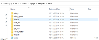
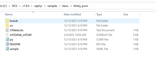
I am using the SDK on VS Code and I find it a bit troubling how things works with Zephyr. I started on a standard blinky but I can't find any examples using Zephyr for a PWM or interrupt based events. So far my attempts at getting along the new SDK was applying changes in the zephyr.dts file : 

		pwm0: pwm@4001c000 {
			compatible = "nordic,nrf-pwm";
			reg = < 0x4001c000 0x1000 >;
			interrupts = < 0x1c 0x1 >;
			status = "okay";
			label = "PWM_0";
			#pwm-cells = < 0x1 >;
			ch0-pin = < 14 >;
			ch0-inverted;
			ch1-pin = < 15 >;
			ch1-inverted;
			ch2-pin = < 16 >;
			ch3-inverted;
			phandle = < 0x5 >;
		};
		
........................
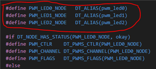
	pwmleds {
		compatible = "pwm-leds";
		pwm_led0: pwm_led_0 {
			pwms = < &pwm0 14 >;
			label = "Voyant Rouge";
		};
		pwm_led1: pwm_led_1 {
			pwms = < &pwm0 15 >;
			label = "Voyant Vert";
		};
		pwm_led2: pwm_led_2 {
			pwms = < &pwm0 16 >;
			label = "Voyant Bleu";
		};
	};
I am then very concerned about the way to proceed, the blink exemple seems to use deprecated GPIO definitions (device_get_binding()) and I am not able to set up anything easily.
I hope you can make my way into this easier.
Best Regards,
Charles
  • Hi again,

    It seems I missed a the exemple related to my needs.I found the basic exemples and I can now interact properly with the board.

    However, I am still confused about the right behavior in NCS. Is there a way to modify GPIO without touching the basic configuration ? It doesn't feel right to change this kind of file.

    Best regards,

    Charles 

  • Hi Charles,

    As a beginner to the nRF Connect SDK, I can understand your confusion as it is quite different from your previous environment. But once you get the hang of it, it gets very convenient. I would recommend you to take a look at all the parts of our Getting Started Guide. Even though 2 specific boards are mentioned here, the working is quite similar to all the DKs. 

    In order to begin with the VS Code extension, we have a tutorial series on Youtube.

    There is blinky and blinky_pwm sample in Zephyr as shown below:

    You can try implementing all this. But Kindly go through the guides and before you begin everything just make sure you have the nRF Connect SDK installed properly. First you should install the nRF Command Line Tools, and then you could try installing the nRF Connect for Desktop

    Also, in the Guide, there is a detailed explanation of creating overlay files and working with the various pins etc so as to not make any direct modifications to the devicetree.

    Regards,

    Priyanka

  • Hi again,

    I am getting the hang a how to deal with many things in the SDK but I still can't add functionnalities as I wish.

    I tried to add node using an overlay the same way I did previously but it seems it does not work.

    EDIT : 

    To be precise, I started from the PWM_blinky exemple.

    Then I added the files device_overlay.overlay and device_conf.conf (this one is empty for now).

    Overlay: 

    / {
        aliases {
            pwm_led0 = &pwm_led0;
            pwm_led1 = &pwm_led1;
            pwm_led2 = &pwm_led2;
        };
    
        &pwm0 {
            status = "okay";
            ch0-pin = <13>;
            ch0-inverted;
            ch1-pin = <14>;
            ch1-inverted;
            ch2-pin = <15>;
            ch2-inverted;
        };
    
        pwmleds {
            compatible = "pwm-leds";
            pwm_led0: pwm_led_0 {
                pwms = <&pwm0 13>;
                status = "okay";
            };
            pwm_led1: pwm_led_1 {
                pwms = <&pwm0 14>;
                status = "okay";
            };
            pwm_led2: pwm_led_2 {
                pwms = <&pwm0 15>;
                status = "okay";
            };
        };
    };

    I added the following lines in the CMaleLists.txt : 

    set(DTC_OVERLAY_FILE
      ${CMAKE_CURRENT_SOURCE_DIR}/device_overlay.overlay
    )
    set(CONF_FILE
      prj.conf
      ${CMAKE_CURRENT_LIST_DIR}/device_conf.conf
    )

    Then I modified the main.c by adding these lines: 

    #if DT_NODE_HAS_STATUS(PWM_LED1_NODE, okay)
    #define PWM1_CTLR	    DT_PWMS_CTLR(PWM_LED1_NODE)
    #define PWM1_CHANNEL	DT_PWMS_CHANNEL(PWM_LED1_NODE)
    #define PWM1_FLAGS   	DT_PWMS_FLAGS(PWM_LED1_NODE)
    #else
    #error "Unsupported board: pwm-led1 devicetree alias is not defined"
    #define PWM1_CTLR	    DT_INVALID_NODE
    #define PWM1_CHANNEL   	0
    #define PWM1_FLAGS    	0
    #endif
    
    #if DT_NODE_HAS_STATUS(PWM_LED2_NODE, okay)
    #define PWM2_CTLR	        DT_PWMS_CTLR(PWM_LED2_NODE)
    #define PWM2_CHANNEL	    DT_PWMS_CHANNEL(PWM_LED2_NODE)
    #define PWM2_FLAGS	        DT_PWMS_FLAGS(PWM_LED2_NODE)
    #else
    #error "Unsupported board: pwm-led2 devicetree alias is not defined"
    #define PWM2_CTLR	    DT_INVALID_NODE
    #define PWM2_CHANNEL  	0
    #define PWM2_FLAGS	    0
    #endif

    and modifying the first PWM accordingly.

    When I try to bulid the application I get the error message : 

    synthax error*

    FATAL ERROR: Unable to parse input tree

    Best Regards,

    Charles

  • Hi Charles,

    So first, you need to check whether you have named the overlay file's right. Which DK are you working with? In case you are using a nRF52840DK, you should name your overlay file "nrf52840dk_nrf52840.overlay". Exception is in the case of nrf5340, for which you name it as "nrf5340dk_nrf5340_cpuapp.overlay". Basically, you name it after the board. 

    Next, you don't have to modify the CMakeLists or prj.conf. The overlay files will be detected and used to modify the devicetree if you put the overlay file in the the project file. It should look something like this:

    You could also place your overlay files inside the "boards" folder (that would be more clean Slight smile)

    Now you can see in your main.c, the line #if DT_NODE_HAS_STATUS(PWM_LED1_NODE, okay). But the compiler has not seen PWM_LED1_NODE defined before, and the same applies for PWM_LED2_NODE . So, you could try defining those too in the main.c as follows:

    Also, try modifying the 'aliases' in your overlay as follows:

    {
        aliases {
            pwm-led0 = &pwm_led0;
            pwm-led1 = &pwm_led1;
            pwm-led2 = &pwm_led2;
        };

    Regards,

    Priyanka

  • Hi,

    I tried renaming the overlay. It seems the problem lies within the synthax of my overlay because I have the same issue.

    I did add the DT_ALIAS but I did not mention it ....

Related