This discussion has been locked.
You can no longer post new replies to this discussion. If you have a question you can start a new discussion

Using the External Antenna Connector (MM8130–2600) on an external antenna.

Hello!

We are planning on using the nRF52832 DK together with an external antenna. We are highly interested in the readings being as accurate as possible, and we are wondering about;

1, Is there a standard or a suitable cable that can be used together with this connector -> coax?

2, Referencing to this post: (https://devzone.nordicsemi.com/f/nordic-q-a/52623/switch-antenna-connector), where the first reply mentioned that the connector is not suitable for an end product, and its more of a test connector. How do we make this connector reliable, or do we have to solder on a extra connector for coax?

Thank you in advance! 

-Anders K

Parents
  • Hi Anders,

    MXHS83QE3000 is a test cable which fits the MM8130-2600 SWF connector.

    But the main problem with using this connector for a and product is that the test cable is not secured in the connector, and any stress put on the cable will result in the cable being disconnected from the connector.

    Your main options are to remove the SWF connector and either replace it with a U.FL connector or solder a coaxial cable to the 50 Ohm transmission line.

    When we take conducted radio measurements of customer devices we cut the transmission line after the radio matching network and solder a rigid coaxial cable to the transmission line. In order to get good connection the outer ground of the coaxial cable is soldered to the ground plane close to the transmission line.


    Best regards,

    Bendik


  • Hello, Bendik!

    Thank you for the fast reply!

    Would you be able to, more in-depth, explain how we are going to conduct this modification on the board? Is it preferred using a U.FL connector or soldering on a coax, cable to the board? And how would these two options affect the RF-readings from the antenna?

Reply
  • Hello, Bendik!

    Thank you for the fast reply!

    Would you be able to, more in-depth, explain how we are going to conduct this modification on the board? Is it preferred using a U.FL connector or soldering on a coax, cable to the board? And how would these two options affect the RF-readings from the antenna?

Children
  • Hi again Anders,

    Just a head up, when you verify a answer the case get closed.


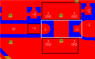
    Here is a diagram of how you could modify the PCB for using a U.FL connector:

    Within the black area you can remove the solder mask by scraping it off, and within the white area you should remove the pieces of the trace and the ground layer by cutting the copper and lifting it off the substrate.

    The U.Fl connector can then be soldered to the trace and to the ground plane. The exact position and size of the solder pads is determined by the foot print of the U.FL connector.


    Soldering a coaxial cable to the trace would be done similarly, by exposing the copper of both the trace and the ground plane at the end of the trace and soldering the center conductor of the cable to the trace and the outer shielding to the ground plane. When using this option it is important that the sickout of the center conductor is kept as short as possible, ideally it should not be any longer than 0.5mm.


    Both options would yield similar results, with a slight decrease in transmitted power due to a potential impedance miss match cause by the modifications.


    Best regards,

    Bendik

Related