This discussion has been locked.
You can no longer post new replies to this discussion. If you have a question you can start a new discussion

Programming a custom PCB with host MCU and Murata MBN52832 through NRF52DK P20 pins. ( "No idcode detected" Error)

Hello. I have a custom board which contains S32K148 MCU and Murata MBN52832 BLE Module and several other modules like GPS, LTE etc. Board is powered via external 12 V adapter but through voltage regulators modules are powered with 3.3V.

I am using SEGGER Embedded Studio as IDE.

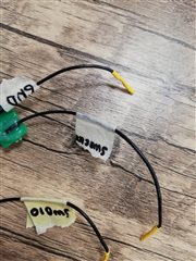
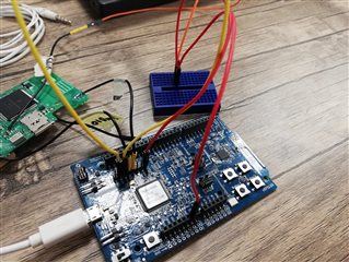
I am trying to program MBN52832 module through its SWD pins using NRF52DK's P20 pins and pin connections goes like this:

P20.SWDIO          ---->  Custom Board SWDIO

P20.SWCLK         ---->  Custom Board SWCLK

P20.VTG               ---->  P20.VDD (To activate external flashing)

P20.GND Detect   ---->  Custom Board GND ( Custom board and NRF52DK have common grounds on a breadboard )

Now the problem is when I try to flash my code into custom PCB I get the following error.

"Failed to connect to target. No idcode detected. Please check connection and Target Interface Type."

I have read almost every post about external programming on here DevZone but the suggested solutions on other posts did not work for my problem.

I double-checked the board for soldering problems etc.

Application works fine on NRF52DK's internal NRF52832 SoC so I do not think it's a software based problem.

I'd appreciate any suggestion regarding this matter. Thanks in advance.

Best regards,

Furkan


Parents
  • Hi Furkan,

    No idcode detected indicates that the debugger is unable to communicate with the target IC. This usually means that there is a connection problem, or that the IO voltages don't match. Can you measure the voltage on the SWDIO pad on your custom board when it is powered but not connected to the debugger? The SWDIO line has an internal pull-up hand should therefore match the VDD voltage on your board. 

    Best regards,

    Vidar

  • Hi Vidar,

    Thanks for your reply. I measured the voltage on SWDIO and got the result of 3.31 Volts

    Best regards,

    Furkan

  • Hi Furkan,

    The log did not provide any additional clues, unfortunately. It shows the same problem where the programmer is unable to communicate with the target.

    Another thing you may try is to reduce the clock speed. This may help if you have long programming cables.

    e.g.

    $ nrfjprog --recover -c 125 // 125 KHz SWDCLK

    Could you also include a picture of your setup?

    Best regards,

    Vidar

  • Hi Vidar,

    Sorry for late response I was on leave from work for a few days. 

    I tried reducing the clock speed but it did not help. We also tried some other connection setups. We broke out custom boards 3.3 V line to be able to supply the MBN52832 from DK and to avoid voltage differences on 3 V lines but we still cant get to program the module. You can see my setup in images below. I cant provide a full photo of custom board due to privacy issues but the thing is SWDIO, SWDCLK and GND pins are break-out pins from custom board.

    I read in other posts that RESET and SWO pins are unnecessary for external programming. But I am wondering if they could help me solve my problem. 

    And my colleague had an idea. MBN52832 module's UART line is connected to S32K148 MCU. Could it prevent the module from communicating through SWD pins? ( Just a thought ).

    Best regards,

    Furkan

  • Hi Furkan,

    Reset and SWO are optional, and SWO is rarely used anyway. The UART lines should not be a problem either. 

    Do you have only one board to test on?

    Best regards,

    Vidar

  • Hi Vidar,

    Unfortunately yes I have only one board to test on, at least for now. 

    I watched the voltage change on SWDCLK and SWDIO pins (pin 25 and 26) of DK's internal SoC with an oscilloscope while flashing the chip just to see what I'm expecting from the module on my custom board. I can see clear square signals on the pins and SWDIO starts from HIGH state and SWDCLK starts from LOW state, but when I measured the SWDCLK pin on the MBN52832 module I got 3.3 Volts. I read that nRF52832 has internal pull-up resistor on SWDIO and internal pull-down resistor on SWDCLK pins. Could this be a problem? If so I'll ask my hardware team colleagues to check the module's connection again.

    Best regards,

    Furkan

  • Hi Furkan,

    Yes, you are right, there CLK line should be low due to the internal pull up. Is there any chance it may be connected to the wrong pin on the module?

    Best regards,

    Vidar

Reply Children
Related