Programming a custom board with an NRF52840 dev kit

Hi,

I've made my own PCB with an nrf52840. Right now I'm hoping to test out the bluetooth and measure my board's power consumption - the only problem is that I can't reliably program the microcontroller! A long time ago I was able to program this device with ble_app_blinky so I know the bluetooth works - unfortunately, right now I keep running into JLink errors. The specific setup/issues are listed below:

Right now I'm trying to program my custom board/NRF with 2 example projects: blinky and ble_app_blinky. To do so, I've setup the boards as in the diagram below:
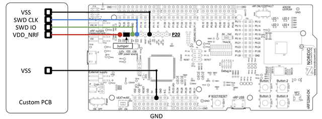
I am powering my custom board with an external supply set to 3.3V (the current limit is set to 3A so we should have more than enough juice) and the dev kit is "powered on" and plugged into my laptop via the uart/usb programming port (the left most usb port on the diagram). With this setup I can reliably program my custom board with the normal blinky program. Unfortunately, when I try to build&debug on my board with ble_app_blinky I get the following error:


Preparing target for download
Executing Reset script TargetInterface.resetAndStop()
Reset: Halt core after reset via DEMCR.VC_CORERESET.
Reset: Reset device via AIRCR.SYSRESETREQ.
Downloading ‘s140_nrf52_7.0.1_softdevice.hex’ to J-Link
Programming 2.7 KB of addresses 00000000 — 00000aff
Programming 149.3 KB of addresses 00001000 — 00026597
Failed to download application.
Error during program/erase phase.
Please check J-Link and target connection.
Download failed

sometimes when I "build & run" directly I get a slightly different error:

Reset: Halt core after reset via DEMCR.VC_CORERESET.
Reset: Reset device via AIRCR.SYSRESETREQ.
Downloading ‘s140_nrf52_7.0.1_softdevice.hex’ to J-Link
Programming 2.7 KB of addresses 00000000 — 00000aff
Programming 149.3 KB of addresses 00001000 — 00026597
J-Link: Flash download: Bank 0 @ 0x00000000: 2 ranges affected (4096 bytes)
J-Link: Flash download: Total: 0.652s (Prepare: 0.172s, Compare: 0.027s, Erase: 0.170s, Program & Verify: 0.106s, Restore: 0.175s)
J-Link: Flash download: Program & Verify speed: 37 KiB/s
Failed to download application.
Error during program/erase phase.
Please check J-Link and target connection.
Download failed

I'm using the latest version of the sdk (v17) and s140. To program my board I'm using SES. I have done all my development so far with the nrf52840 dk (PCA10056) and I figured I could use the same example files. Do I have to change the starting/stopping memory locations for programming? If not, does anyone have any suggestions for further log/debug steps I can proceed with?

I beseech the Nordic (company) gods.

Thank you,

Ryan

  • Hi Ryan, 

    Looking at the files there are some tings i want to comment on.

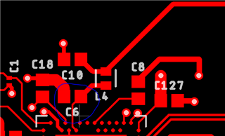
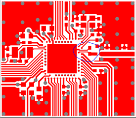
    1. it would be good to have a top layer ground pour. More ground surface area does help reduce return paths and can be used to create coplanar wave guides in sted of strip lines. We do recommend the grounded coplanar wave guide as we have seen that they often preform better.

    2. The decupling cap on the first radio matching component is not directly following the ref. design.  We do have some notes that point to the fact that it is not just matching but also filering of the harmonics so it is best to keep the layout identical. You do have more then enough space to do a copy past of the design. 


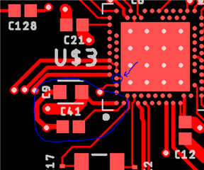
    3. Since there is no top layer ground you are also missing out on the some of the pinns that benefit from being connected to top layer ground might give reduced radio performance. The decupling caps here help filter the supply so that no as lite noise as possible can get to the radio.


    ryerye120 said:
    close as possible to the CKAA WLCSP schematic #3

    Did you mean QIAA  no. 3?  aQFN package, in your design that is what is used at least. 


    But i think the layout is ok, adding top layer ground would solve many of the "issues", choice of antenna is good also, many use it and it preforms well.


    As for the application halting after reset issue, i have not figured this out, so will update in a day or two to wit more info\debugging options you can test. Sorry for the slow response.  

    Regards,
    Jonathan

  • Hi Jonathan,

    Did you mean QIAA  no. 3?  aQFN package, in your design that is what is used at least. 

    Sorry, you're right. We're using the aQFN packaged chips. The most important point was that we are powering the chip with an external regulator & originally wanted to have the USB interface (but I'm pretty sure we ended up scraping that and just left the USB interface pulled up/down - whatever it needed to be)

    But i think the layout is ok, adding top layer ground would solve many of the "issues", choice of antenna is good also, many use it and it preforms well.

    We'll definitely incorporate this in our next board!! Thank you for the suggestion.

    As for the application halting after reset issue, i have not figured this out, so will update in a day or two to wit more info\debugging options you can test. Sorry for the slow response.  

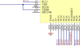
    No worries, I figure it is a weird bug. Could it be related to how we've wired VDD and VDDH? I'm wondering if I missed a power connection.

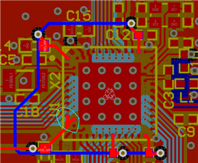
  • Hi Ryan, here is the ref design, and compared to yours it does not differ that much, so i dont think it is the issue. 

    So does not look like you have a missed power connection. 


    Maybe try a different SDK version or different SDK? see if the behaviour is still the same. And have you tested on more then one custom board?

    Regards,
    Jonathan

  • Hi Jonathan,

    I've tried multiple boards and they all have this issue. We even re-spun the boards (for other reasons) and the re-spun boards have the same issue.

    I've tried it with SDK 16 and it had the same issue.

    Is there a reference design Eagle Project that I could maybe get access to? If so, maybe I can just plop that directly into our design?

    Kindest regards,

    Ryan

  • Hi Ryan, 

    We dont have a Eagle version, only Altium. 

    Can you probe VDD? what is the supply voltage. 
    Might be some supply issue or decupling issue but its strange. 


    If the USB supply is not used then DECUSB can be left floating and VBUS pin pulled down to ground. 


    Regards,
    Jonathan

Related