This discussion has been locked.
You can no longer post new replies to this discussion. If you have a question you can start a new discussion

Zephyr -Facing problem in digital read implementation for the pin which is used as INPUT

Hello,

I am using the nRF 52840 DK board. I am trying to implement the code for the HX711 in Zephyr.

I was just comparing the code with Arduino which I have written and it is the minimum basic code to check working of HX711 on arduino. Here is the code of Arduino.


// HX711 circuit wiring
const int LOADCELL_DOUT_PIN = 15;
const int LOADCELL_SCK_PIN = 18;


void setup() {
  Serial.begin(115200);
  pinMode(LOADCELL_SCK_PIN, OUTPUT);
  pinMode(LOADCELL_DOUT_PIN, INPUT);
}
uint8_t shiftInSlow(uint8_t dataPin, uint8_t clockPin, uint8_t bitOrder) {
    uint8_t value = 0;
    uint8_t i;

    for(i = 0; i < 8; ++i) {
        digitalWrite(clockPin, HIGH);
        delayMicroseconds(1);
        if(bitOrder == LSBFIRST)
            value |= digitalRead(dataPin) << i;
        else
            value |= digitalRead(dataPin) << (7 - i);
        digitalWrite(clockPin, LOW);
        delayMicroseconds(1);
    }
    return value;
}
void loop() {

unsigned long value = 0;
  uint8_t data[3] = { 0 };
  uint8_t filler = 0x00;


  data[2] = shiftInSlow(LOADCELL_DOUT_PIN, LOADCELL_SCK_PIN, MSBFIRST);
  data[1] = shiftInSlow(LOADCELL_DOUT_PIN, LOADCELL_SCK_PIN, MSBFIRST);
  data[0] = shiftInSlow(LOADCELL_DOUT_PIN, LOADCELL_SCK_PIN, MSBFIRST);

  // Set the channel and the gain factor for the next reading using the clock pin.
  for (unsigned int i = 0; i < 1; i++) {
    digitalWrite(LOADCELL_SCK_PIN, HIGH);

    delayMicroseconds(1);

    digitalWrite(LOADCELL_SCK_PIN, LOW);

    delayMicroseconds(1);

  }

  Serial.print(" data[0] : ");
  Serial.print(data[0]);
  Serial.print(" data[1] : ");
  Serial.print(data[1]);
  Serial.print(" data[2] : ");
  Serial.println(data[2]);

  delay(1000);
 
}

I have checked it in ESP32 and it works fine and its output is as shown below:

11:33:32.407 ->  data[0] : 155 data[1] : 103 data[2] : 0
11:33:33.404 ->  data[0] : 168 data[1] : 103 data[2] : 0
11:33:34.402 ->  data[0] : 200 data[1] : 103 data[2] : 0
11:33:35.400 ->  data[0] : 201 data[1] : 103 data[2] : 0
11:33:36.396 ->  data[0] : 227 data[1] : 103 data[2] : 0
11:33:37.427 ->  data[0] : 239 data[1] : 103 data[2] : 0
11:33:38.424 ->  data[0] : 211 data[1] : 103 data[2] : 0
11:33:39.421 ->  data[0] : 129 data[1] : 103 data[2] : 0
11:33:40.417 ->  data[0] : 114 data[1] : 103 data[2] : 0
11:33:41.413 ->  data[0] : 135 data[1] : 103 data[2] : 0
11:33:42.411 ->  data[0] : 117 data[1] : 103 data[2] : 0

So I have taken the reference of above my code and tried to write code in Zephyr below.

#include <zephyr.h>
#include<sys/printk.h>

#include <sys/util.h>
#include <sys/byteorder.h>
#include <drivers/gpio.h>
#define PD_SCK 26
#define DOUT 31

#define LSBFIRST 0
#define MSBFIRST 1
#define SW0_NODE DT_ALIAS(sw0)
struct device *dev;
static const struct gpio_dt_spec DOUTINPUT = GPIO_DT_SPEC_GET_OR(SW0_NODE, gpios,{0});
uint8_t shiftInSlow( uint8_t clockPin, uint8_t bitOrder) {
uint8_t value = 0;
uint8_t i;

for(i = 0; i < 8; ++i) {
gpio_pin_set(dev,clockPin, 0);
k_sleep(K_USEC(1));
value |= !gpio_pin_get_dt(&DOUTINPUT) << (7 - i);
gpio_pin_set(dev,clockPin, 1);
k_sleep(K_USEC(1));
}
return value;
}
void begin() {

int ret;

dev = device_get_binding("GPIO_0");
if (dev == NULL) {
printk("Unable to bind");
return;
}

ret = gpio_pin_configure(dev, PD_SCK, GPIO_OUTPUT_ACTIVE);
if (ret < 0) {
printk("Unable to config pin PD_SCK");
return;
}
ret = gpio_pin_configure_dt(&DOUTINPUT,GPIO_INPUT | GPIO_PULL_UP);
if (ret < 0) {
printk("Unable to config pin DOUT");
return;
}
}

void main(void)
{
printk("Started");
begin();
while(1){

unsigned long value = 0;
uint8_t data[3] = { 0 };
uint8_t filler = 0x00;


data[2] = shiftInSlow( PD_SCK, MSBFIRST);
data[1] = shiftInSlow( PD_SCK, MSBFIRST);
data[0] = shiftInSlow( PD_SCK, MSBFIRST);

// Set the channel and the gain factor for the next reading using the clock pin.
for (unsigned int i = 0; i < 1; i++) {
gpio_pin_set(dev,PD_SCK, 0);
k_sleep(K_USEC(1));
gpio_pin_set(dev,PD_SCK, 1);
k_sleep(K_USEC(1));
}

printk("data[0] : %d | data[1] : %d |data[2] : %d \n",data[0],data[1],data[2]);
k_sleep(K_MSEC(1000));
//printk("sleep complete");
}
}

nrf52840dk_nrf52840.overlay file looks like this:

/ {
aliases {
sw0 = &buttona0;
sw1 = &buttona1;

};
gpio_keys {
compatible = "gpio-keys";
buttona0: button_0 {
gpios = <&gpio0 31 GPIO_ACTIVE_LOW>;
label = "Button 0";
};
buttona1: button_1 {
gpios = <&gpio1 3 GPIO_ACTIVE_LOW>;
label = "Button 1";
};
};


};
/*&uart0 {
compatible = "nordic,nrf-uarte";
status = "okay";
current-speed = <115200>;
tx-pin = <5>;
rx-pin = <4>;
rx-pull-up;
rts-pin = <5>;
cts-pin = <7>;
cts-pull-up;
};*/

&i2c0 {
compatible = "nordic,nrf-twim";
status = "okay";
sda-pin = <29>;
scl-pin = <31>;
clock-frequency = <I2C_BITRATE_FAST>;
mpu9250@68 {
compatible = "invensense,mpu9250";
reg = <0x68>;
status = "okay";
label = "MPU9250";
int-gpios = <&gpio0 11 GPIO_ACTIVE_HIGH>;
};
};

Output of above code is

data[0] : 0 | data[1] : 0 |data[2] : 0

I think the culprit of the above issue is the below statement in the code

!gpio_pin_get_dt(&DOUTINPUT)

gpio_pin_get_dt() is not doing the work like digitalRead() does in 1st example.

May I know what is the difference between gpio_pin_get_dt() and digitalRead() ?

Am I doing anything wrong?

Thanks in advance.

Thanks and regards,

Neeraj Dhekale

Parents
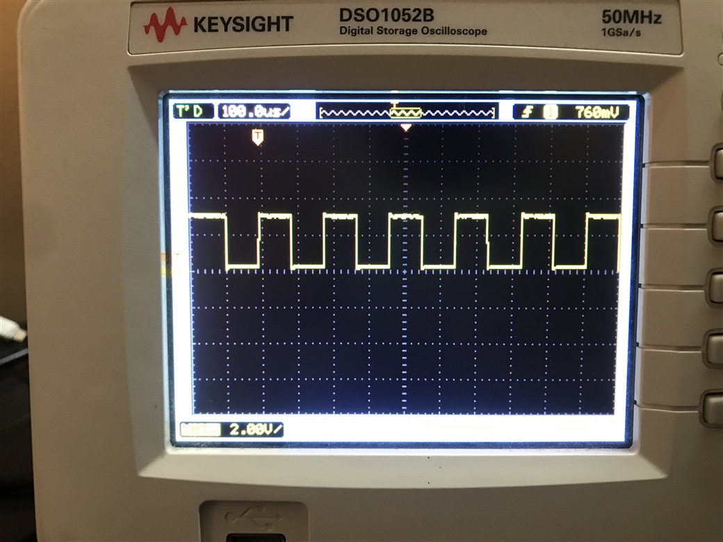
  • I was checking the PD_SCK pin on DSO as per code it should have ~1 microsecond but after checking it on DSO I am getting it in 100 microseconds.

    I am trying to make it <100 microseconds by using k_sleep(K_NSEC(1); or k_sleep(K_NSEC(100); it remains at 100 microseconds only.

    How can make it less than 100 microseconds? As per the datasheet of HX711, it should not have less than 50 microseconds.

    Am I doing anything wrong?

    Thanks and regards,

    Neeraj Dhekale

  • Hi Neeraj, sorry for the late reply.

    The HX711 sensor is not standard I2C and requires some work. However, it looks like much of the work is done. You might be able to copy the code and run the example:

    Avia HX711 driver and example: https://github.com/zephyrproject-rtos/zephyr/pull/42570 

    Best regards,

    Håkon

Reply Children
  • Thanks, Helsing,

    Thanks for your reply.

    Noted. Yes after understanding the limitation of Zephyr I have switched it to Softdevice and their, code works perfectly fine without any issue.

    Thanks and regards,

    Neeraj Dhekale