NRF52810 Softdevice S112, GPIO P14 OUTSET failure after SD enabled

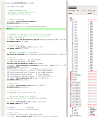
I think I may have found errata. Using the combination in the title I can enable output, verified at the pin using OUTSET. Once the softdevice is enabled the same command fails to set the pin. You can see this in the screenshot where I've moved it below the SD command that induces the error.

I haven't tested other pins as it's difficult to do on a pre-production board. 

I've scoured the web and can't find anything about this pin being blocked, indeed SD is not supposed to touch GPIO at all. 


Parents Reply Children
  • I don't see any errors, but there's no output on the pin when attempting to set after enabling SD.

    Versions - SD7.2, SDK 16


  • Hi there,

    Are you using a custom board or a development kit? If the former, is there any external pullups or pulldowns connected to the pin? The correct way of setting a pin:

    nrf_gpio_cfg_output(pin);
    nrf_gpio_pin_set(pin);

    regards

    Jared 

  • Hi, no pull-ups/downs.

    I am using direct commands not sdk. These are the two relevant sets.

      NRF_GPIO->PIN_CNF[CFG_PIN_SYSTEM_ACTIVE] = pinDisconnectInputBuffer | (GPIO_PIN_CNF_DIR_Output << GPIO_PIN_CNF_DIR_Pos) | (GPIO_PIN_CNF_DRIVE_S0S1 << GPIO_PIN_CNF_DRIVE_Pos);
      
      NRF_GPIO->OUTSET = 1 << CFG_PIN_SYSTEM_ACTIVE;


    I'm using a custom pre-production board but that's not relevant.

  • Hi,

    I tried this and it worked fine after enabling the BLE stack:

        NRF_GPIO->PIN_CNF[14] = (GPIO_PIN_CNF_DIR_Output << GPIO_PIN_CNF_DIR_Pos)
                                   | (GPIO_PIN_CNF_INPUT_Disconnect << GPIO_PIN_CNF_INPUT_Pos)
                                   | (GPIO_PIN_CNF_PULL_Disabled << GPIO_PIN_CNF_PULL_Pos)
                                   | (GPIO_PIN_CNF_DRIVE_S0S1 << GPIO_PIN_CNF_DRIVE_Pos)
                                   | (GPIO_PIN_CNF_SENSE_Disabled << GPIO_PIN_CNF_SENSE_Pos);


      NRF_GPIO->OUTSET = 1 << 14;
    

    Are you measuring physically on the pad of the pin? What voltage do you measure? Is there anything else connected to the pin?

    regards

    Jared 

  • Yes physically measuring on the pin. Nothing of relevance (no sink) attached to the pin. It was literally do the set above the BLE command and it would work, move it one line below and it wouldn't.

    I've since changed the BLE code around a bit and initially it now appears to be working, which I can't explain at all, but I have a further testing on it later today.

    I wonder if GPIO won't set without something the BLE controls, specially I'm thinking that BLE starts LF clock. This is the one change I have made since, I was relying on BLE to start this clock but I'm using RTC1 outside of BLE control so now start LF manually. 

Related