nrf21540 SPI communication voltage level problem

Hi

I connected the nRF21540 to a nRF52840 like in the application notes.

Here is the schematic:

I implemented the driver and now I try to communicate over the SPI with the nRF21540.

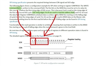
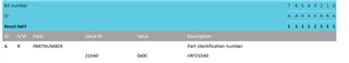
First, I try to read the Partnumber. When I set the power dowen off, the SPI signals are ok, but of course I have no feedback from the MISO.

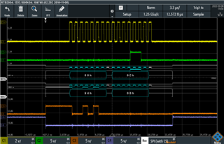
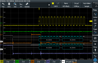
yellow is the SP I Clock, green is MISO, orange is MOSI, lila is ChipSelect

Signals ok:

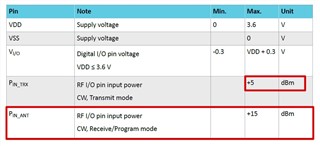
As soon as I set PowerDown = ON = nRF21540 enabled, the second SPI MOSI pulse is there, but really low (nRF21540 pulls down the level!)

What is the reason of this and how this can be solved?

Reagrds

  • ok, and to set the nrf21540 in PG mode, I have to send over SPI

    Write Enable to field UICR_EN in register CONFREG1 to enable UICR Program state. -> 0xC1 0x04

    Write Enter to field KEY in register CONFREG1 to enter UICR Program state. -> 0xC1 0xF4

    Read the PartNumber -> 0x94 0x00

    -> still no Feedback on the MISO line!

    Whats wrong? There are only some commands, It can't be so difficult to read out the PartNumber. Can you please tell me what is missing in the communication codes or which PIN is special to drive or anything else?

  • If I like to write in CONFREG1 0x1, the first byte will be:

    0b11 (write) 10 000 (Confreg1) = 0b1110 0000 = 0xE0?

    A value for CONFREG0 can be 0x7C = 0b0111 1100 ?

                                                    //TX disabled, TX_Gain = POUTA,
                                                    //TX_GAIN TX gain = 31 control (0: minimum, 31: maximum)

  • Its running now, i had a problem with the chip and the MISO / MOSI Pin definition.

    Here is the feedback for the PartNumber (0x0C)

    PartNumber reading

    What should be the Input Power from the nRF52840 to the nRF21540? +0dB? or can I use +8dB or will this destroy the nRF21540?

    In the datasheet its written max +5dBm. Pin_Ant is max +15dBm, but this is an output PIN. How should this be interpreted?

    Thanks for reply

  • Hi

    I'm measuring the RF dBm and saw that Confreg0 can change the TX gain like in the datasheet.

    But when I write 0x7F and read back the 0x7F the dBM in the same range is about -70dBm. If I set 0xFF to Confreg0 the dBM is about -20dBm. Can anybody explain this? Its not accoring to the datasheet what the nRF21540 should do...

  • Dominik Eugster said:
    What should be the Input Power from the nRF52840 to the nRF21540? +0dB? or can I use +8dB or will this destroy the nRF21540?

    Max input on pin10(TRX) of the nRF21540  is +5dBm(before taking permanent damage), so that would be the output power from the nRF52840 in your case. Recommend to use +0dBm. 


    Dominik Eugster said:
    Pin_Ant is max +15dBm, but this is an output PIN.

    Correct this is the antenna pins, so ANT 1(pin 2) and ANT 2(pin 3). +15dBm is the limit where it could be damaged if the ANT pin is exposed to greater then +15dBm. 

    Regards,
    Jonathan

Related