This discussion has been locked.
You can no longer post new replies to this discussion. If you have a question you can start a new discussion

Zephyr UART on Fanstel BLG840F

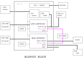
I am using UART on the Fanstel BLG840F to communicate from the 9160 to the 52840.  So far I have successfully been able to communicate from the 52840 to the 9160 but have not been able to send UART messages back from the 9160 to the 52840.  I am using shared UART functions between the boards with a single function to handle sending:

int uart_send(struct uart_data_t *uart_data)
{
    int status = uart_tx(device_uart, uart_data->data, uart_data->length, SYS_FOREVER_MS);

    if (status != 0)
    {
        printk("uart_tx ( error: %d )\n", status);

        // Add to tx queue to try and process / send later ...
        k_fifo_put(&fifo_uart_tx_data, uart_data);
    }
    printk("data sent: %s \n", uart_data);

    return status;
}

and a registered event handler:

static void on_uart_event(const struct device *dev, struct uart_event *evt, void *user_data)
{
    struct uart_data_t *uart_data;
    static uint8_t *aborted_buf;
    static size_t aborted_len;

    switch (evt->type)
    {
    //put this in ifdef block
    
    case UART_RX_RDY:
    {
        printk("UART_RX_RDY\n");

        uart_data = CONTAINER_OF(evt->data.rx.buf, struct uart_data_t, data); // where does third parameter data come from?

        printk("uart_rx called with data: %s", uart_data->data);
       

        hive_uart_queue_rx_data_buffer(uart_data);

        uart_rx_disable(device_uart); 

        break;
    }
    
    case UART_RX_DISABLED:
    {
        printk("UART_RX_DISABLED\n");

        start_receiving();

        break;
    }
    case UART_RX_BUF_REQUEST:
    {
        printk("UART_RX_BUF_REQUEST\n");

        struct uart_data_t *uart_data = hive_uart_allocate_data_buffer();

        if (uart_data == NULL)
        {
            break;
        }

        uart_rx_buf_rsp(device_uart, uart_data->data, sizeof(uart_data->data));

        break;
    }
    case UART_RX_BUF_RELEASED:
    {
        printk("UART_RX_BUF_RELEASED\n");

        uart_data = CONTAINER_OF(evt->data.rx_buf.buf, struct uart_data_t, data);

        k_free(uart_data);

        break;
    }
    case UART_TX_DONE:
    {
        printk("UART_TX_DONE\n");

        if ((evt->data.tx.len == 0) || (!evt->data.tx.buf))
        {
            return;
        }

        if (aborted_buf)
        {
            uart_data = CONTAINER_OF(aborted_buf, struct uart_data_t, data);
            aborted_buf = NULL;
            aborted_len = 0;
        }
        else
        {
            uart_data = CONTAINER_OF(evt->data.tx.buf, struct uart_data_t, data);
        }

        k_free(uart_data);

        // See if there's anything waiting in the queue ...
        uart_data = k_fifo_get(&fifo_uart_tx_data, K_NO_WAIT);

        if (!uart_data)
        {
            return;
        }

        if (uart_tx(device_uart, uart_data->data, uart_data->length, SYS_FOREVER_MS))
        {
            printk("(UART_TX_DONE) Failed to send data over UART\n");

            // Add back to queue to try again ...
            k_fifo_put(&fifo_uart_tx_data, uart_data);
        }

        break;
    }
    case UART_TX_ABORTED:
    {
        if (!aborted_buf)
        {
            aborted_buf = (uint8_t *)evt->data.tx.buf;
        }

        aborted_len += evt->data.tx.len;

        uart_data = CONTAINER_OF(aborted_buf, struct uart_data_t, data);

        if (uart_tx(device_uart, &uart_data->data[aborted_len], uart_data->length - aborted_len, SYS_FOREVER_MS))
        {
            printk("(UART_TX_ABORTED) Failed to send data over UART\n");

            // Add to queue to try again later ...
            k_fifo_put(&fifo_uart_tx_data, uart_data);
        }

        break;
    }
    default:
    {
        printk("UART event received: %d\n", evt->type);
        break;
    }
    }
}

Calling the UART send function on the 52840 triggers the UART_RX_RDY case correctly on the 9160, but calling the UART send function on the 9160 does not trigger the UART_RX_RDY on the 52840.  Does each board need a separate event handler and separate UART function or can they be shared in this way and I have setup something on the 9160 side incorrectly?

Thanks

Parents
  • Hi Jake,

    Thank you for the request. Just letting you know I have starting to look into this. I will get back to you tomorrow or the day after.

    Best regards,

    Håkon

  • Just wanted to update with some tests I ran.  I also realized I didn't post the entire uart event handler in the first post and have since updated it (the second code block in the original post):

    I verified that on the 9160 the data and length are being read correctly and the uart_tx function is returning 0, so the send seems to be functioning correctly.

    On the 52840 side it seems that the event handler registered using uart_callback_set is not being called even tho the uart_tx is sending without error.  I know the pins are configured correctly too since it works as expected sending from the 52840 to the 9160.

  • Hi Jake

    Håkon is currently unavailable, and I will handle the case instead. 

    Have you checked with a scope or logic analyzer whether or not the data is actually sent over the bus, from the 9160 to the 52840?

    Do you know if flow control is used or not?

    Best regards
    Torbjørn

  • I'm using the Fanstel BLG840X and I don't think I can access the UART pins for communicating between the boards can I?  I don't see anything on the board that I could easily probe unless there is another way.

  • Hi Jake

    I guess you are right, if the module is encased it would be hard to get access to these pins, unless you break it apart. 

    Would you happen to have a nRF9160DK available that you can test with, or the DK from Fanstel shown in their user guide?

    Best regards
    Torbjørn

  • I have a 9160DK so  I could try and run it on there, I think I would just have to change my overlay file to correct for the different rx and tx pins.  I don't have a logic analyzer but I could get access to one, are they just able to plug into the pins of the 9160DK?  So I would just have to probe the pins being used for UART directly?

  • Hi Jake

    Correct, you need to use pins that are shared between the nRF9160 and the nRF52840, and configure the nRF52840 to enable these pins in the DTS configuration (overlay). 

    I tested this myself, using a simple UART example, to ensure it worked as expected: 
    https://github.com/too1/ncs-uart-async-count-rx/tree/9160dk-91-to-52-uart-test

    Pretty much all you would need to include in your code are those two overlays (for the 9160 and 52840 respectively), and then use UART1 on each side to communicate with the other device. 

    Whichever pins you use they should be accessible on the pin headers, in case you want to check them with the logic analyzer. 

    Best regards
    Torbjørn

Reply
  • Hi Jake

    Correct, you need to use pins that are shared between the nRF9160 and the nRF52840, and configure the nRF52840 to enable these pins in the DTS configuration (overlay). 

    I tested this myself, using a simple UART example, to ensure it worked as expected: 
    https://github.com/too1/ncs-uart-async-count-rx/tree/9160dk-91-to-52-uart-test

    Pretty much all you would need to include in your code are those two overlays (for the 9160 and 52840 respectively), and then use UART1 on each side to communicate with the other device. 

    Whichever pins you use they should be accessible on the pin headers, in case you want to check them with the logic analyzer. 

    Best regards
    Torbjørn

Children
  • Okay, I will work on getting the logic analyzer and testing.  

    Pretty much all you would need to include in your code are those two overlays (for the 9160 and 52840 respectively), and then use UART1 on each side to communicate with the other device.

    I was currently using  DT_LABEL( DT_NODELABEL( uart1 ) ) ) == 0 as my argument for device_get_binding on the 52840 and DT_LABEL( DT_NODELABEL( uart0 ) ) ) == 0 as my argument for device_get_binding on the 9160.  In the 52840 I am using this as my overlay file:

    &uart1 {
    	current-speed = <115200>;
    	status = "ok";
    	tx-pin = <3>;
    	rx-pin = <5>;
    	rts-pin = <40>; // P1.08 = 32 + 8
    	cts-pin = <7>;
    };

    But just noticed I am getting the error: overlapping assignment on pin 5.  It is already being used as the rts-pin for uart0 in the device tree. 

    Might my setup here be an issue? Should I be using UART0 or UART1 for both boards?

    And I assumed UART0 and UART1 were meant to be compatible so I assumed that their pins were configured correctly in the zephyr.dts file, but I still have the overlap error.  Do I need to do something to resolve this?  

  • Hi Jake

    It seems you are trying to set up uart1 to use exactly the same pins as uart0 in the nRF52840 DTS configuration. 

    This is possible, but then you would have to either disable the uart0 interface, or move it to use some other pins. 

    UART0 and UART1 should be completely interchangeable, yes, so in this case you might as well just use uart0 as it is, rather than enable uart1 on the same pins. In my example I use uart1 for the chip to chip communication on both sides, in order to allow me to keep UART logging enabled on uart0 as normal. 

    If you do decide to use uart0 rather than uart1 on the nRF52840 side, keep in mind that uart0 is the default option for logging, the shell and serial bootloader in the DTS file:

    chosen {
    	zephyr,console = &uart0;
    	zephyr,shell-uart = &uart0;
    	zephyr,uart-mcumgr = &uart0;
    	zephyr,bt-mon-uart = &uart0;
    	zephyr,sram = &sram0;
    	zephyr,flash = &flash0;
    };
    If you don't use any of these features this shouldn't be a problem, but if you want to use them you might want to change these to use UART1. 

    Best regards
    Torbjørn

  • It seems you are trying to set up uart1 to use exactly the same pins as uart0 in the nRF52840 DTS configuration.

    I was creating an overlay for uart1.  The overlay I used is the same as uart1 except for the rts pin which was reassigned to 40.  I think I am not understanding how to know which pins to use.  The 52840 is on the BLG840X through the BT840 module which remaps some of the pins.  (datasheet page 14: https://www.mouser.com/datasheet/2/915/BlueNor_BT840F_datasheets-1622692.pdf).

    How do I know which pins are able to connect between the BLG840X 9160 and 52840? 

    My first thought was to try and match the pins used in the sample you referenced on github, but I wasn't sure if the BLG840X uses the same connections.  For instance in the sample's 52840 overlay file it uses P0.20 (AD16)  for the RX-pin.  This pin is listed as E1 in the BT840 datasheet, so how would I remap this in my overlay file for the BLG840X?

  • Hi Jake

    Wouldn't the BLG840X come with its own set of specifications detailing which pins from the nRF9160 are connected to which pins on the BT840?

    Best regards
    Torbjørn

  • They provide this block diagram which has App1-UART of the 9160 connected to nRF52-UART of the BT840F via the JS3 connector.  I looked through the 9160 datasheet and couldn't find any labeling of APP1 so I wasn't sure what that was referring to, and same with nRF52 in its datasheet.  It says that uart pins such as psel.rts can be mapped to pins, but psel.rxd, psel.rts etc. were all mapped to P0.31 so I didn't understand this.  Wouldn't these need to be separate pins physically?

Related