This discussion has been locked.
You can no longer post new replies to this discussion. If you have a question you can start a new discussion

Powering nRF52810 with 3.6V Lithium battery

I have designed some beacons based on nRF52810. The software uses the minimum functionality of the radio to transmit some packets every second and sleep.

In their sleep period the beacon consumes around 2-5uA.

I chose to power the beacons with an ER14250 3.6V Lithium battery, 1200mAh.

During an application testing I deployed around 10 beacons that transmitted a packet to a receiver every second. I noticed some of them drained the battery within days which is not reasonable as they should last over 2 years with that battery.

I tried to investigate the problem further. I programmed a beacon to transmit every 100ms.

A week after I found it dead. The battery was completely drained and also the chip was damaged.

I replaced the battery and it didn't work.

I used a bench power supply at 3.5V to check what was going on and I noticed its current consumption was around 150mA which is an indicator of a faulty chip.

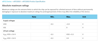
The question is can that battery be used for nRF52810? In the datasheet it says absolute maximum at 3.6V yet in the recommended voltage range it mentions up to 3.6V.

So that's a little confusing as the absolute maximum voltage is the same as the recommended operating voltage.

Can that battery cause damage to the chip?

Parents
  • Hi george,

    Edit: A 3.6V battery voltage should normally not cause any problems. (However, as Pål points out, a 3.6V rechargeable battery could potentially be charged to a higher voltage.)

    Table 131 on page 410 in the product specification for nRF52810 specifies VDD max. to +3.9V.

    Would you be able to share the schematics for your design?

    Have you inspected the boards for any assembly errors? Would you be able to share a photo of the board?

  • Hi helsing,

    The beacon board is based on a chinese module E73-2G4M04S1AX of Ebyte

    Below you can see its internal schematic.

    The version we have makes use of an nRF52810 with an external BLE antenna attached to it. We also added an extra 10uF capacitance.

    I also use the integrated DC/DC after following the reference circuit.

    First, do you think that this capacitance is enough?

    Second, What do you think would cause that damage to the module? I mentioned again that it was found dead after a week.

  • Hi helsing,

    Below you can see the rest of the schematic

    I2C bus and SENSE_ pins are connected to a integrated temp/humid sensor. The sensor can work up to 5.5V

    The rest of the pins you see on the schematic are not connected anywhere.

    I could not find any reason the module died.

    Do you think the total capacitance on the power rail is enough for the transmission peaks?

    Also, I checked with an oscilloscope the current consumption during transmission and the results are very similar to what I see on

     devzone.nordicsemi.com/.../online-power-profiler-for-bluetooth-le

  • Thank you for sharing the schematics.

    It appears as if you might have doubled the capacitance on DEC1. The reference design for nRF52810 recommends a 100nF capacitor on DEC1. However, both the internal schematics of E73-2G4M04S1A that you posted previously(C18), and your own schematics(C7) shows a 100nF capacitor on DEC1. Using the right capacitance on the DEC pins is highly important. I do not know how doubling the capacitance of DEC1 will effect the circuit, however, at this stage I can not rule out this being the cause of your problem.

    Here are a few other thoughts:

    George555 said:
    I2C bus and SENSE_ pins are connected to a integrated temp/humid sensor. The sensor can work up to 5.5V

    How is the temp/humid sensor powered? What is the voltage on the I2C pins from the sensor?

    BAT_MEAS

    How is AIN0 configured internally?

    Could you please measure AIN0 on both the broken and working units? Is it shorted?

    ER14250 3.6V Lithium battery, 1200mAh

    Have you measured the battery voltage in various conditions when brand new? Would you be able to share the datasheet for your specific battery?

    A picture of your PCB or a report from when you are visually inspecting your PCB would still be interesting to hear about.

  • Hi again,

    I also noticed that the schematics that you provided for the module has a 100nF capacitor connected to DEC3. The recommended value according to the reference design is 100pF. As far as I know, this could potentially also cause problems. Could you please somehow try to verify that the schematic you provided for the module is showing exactly what is inside the module?

  • George555 said:
    We also added an extra 10uF capacitance
    George555 said:
    , do you think that this capacitance is enough?

    According to the schematic you provided, the module already has an internal 10uF capacitor(C19). The recommendation is 4.7uF, so this should be more than enough. The product specification states max. and min. rise times for VCC, so it is a good idea to double check that you are within the range.

    Another concern: AIN0 (BAT_MEAS) only has a 0.1uF capacitor. As a consequence, BAT_MEAS will reach 3.6V earlier than VCC. I have not yet checked whether the product specification states that this is OK.

  • Thank you for your help!

    I did not notice those extra capacitors. I added them because I wasn't sure about the internal schematic.

    I also took a picture of the module

    Can you please provide more information regarding the importance of the pins you mentioned?

    Regarding the other questions.

    How is the temp/humid sensor powered? What is the voltage on the I2C pins from the sensor?

    The temp/humid sensor powered directly from the battery. The voltage on the I2C bus is the same as Vbat. SHT31-DIS-B is the part number.

    How is AIN0 configured internally?

    Could you please measure AIN0 on both the broken and working units? Is it shorted?

    Is it configured to work as analog input pin.

    So far, apart from the high percentace of random battery drain on some beacons I have only one dead product in the lab. I checked every pin with a DMM with respect to ground. no one is shorted.

    Have you measured the battery voltage in various conditions when brand new? Would you be able to share the datasheet for your specific battery?

    A brand new battery has 3.6V

    I think that's its datasheet

    https://www.compel.ru/pdf-items/eemb/ps/er14250/854b3cfd8bbc0ca8f0eb7f130ed3f8a8

Reply
  • Thank you for your help!

    I did not notice those extra capacitors. I added them because I wasn't sure about the internal schematic.

    I also took a picture of the module

    Can you please provide more information regarding the importance of the pins you mentioned?

    Regarding the other questions.

    How is the temp/humid sensor powered? What is the voltage on the I2C pins from the sensor?

    The temp/humid sensor powered directly from the battery. The voltage on the I2C bus is the same as Vbat. SHT31-DIS-B is the part number.

    How is AIN0 configured internally?

    Could you please measure AIN0 on both the broken and working units? Is it shorted?

    Is it configured to work as analog input pin.

    So far, apart from the high percentace of random battery drain on some beacons I have only one dead product in the lab. I checked every pin with a DMM with respect to ground. no one is shorted.

    Have you measured the battery voltage in various conditions when brand new? Would you be able to share the datasheet for your specific battery?

    A brand new battery has 3.6V

    I think that's its datasheet

    https://www.compel.ru/pdf-items/eemb/ps/er14250/854b3cfd8bbc0ca8f0eb7f130ed3f8a8

Children
No Data
Related