Problem bringing up a custom board (cant see board outside of bootloader mode)

I have designed a custom board for the nrf52840 and upon testing it in the nrf connect sdk (using a JLink), I can only see the board when it's in bootloader mode. When it's in normal operation, the debugger does not show it. 

Additionally, it does not appear as a USB device although I enabled USB CDC. In fact, I kept the configuration pretty much similar to the nrf52840 dongle when I defined the custom board on the nrf connect sdk.

Has anyone run into a similar issue? Are there any guidelines for how to debug such a problem?

Parents Reply Children
  • I see. So Blinky is also not working. Please continue testing with Blinky, as that is the simplest possible example application and that really should work. As it does not, something is fundamentally wrong.

    1. Can you upload your schematics and layout, and also your Blinky project (with any modifications you have made for your board). That way I can review to see if I see something obvious.
    2. Let me know whatever you find from attempting to debug? What exactly happens? Can you share logs, screenshots, etc, to make tit clearer?
  • Thanks @.

    1. I attached the schematics as well as the custom board I defined withing nrf connect sdk. It was modified from the nrf52840 dongle board definition.

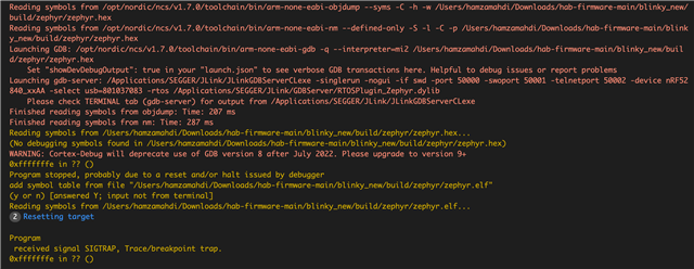
    2. In terms of debugging, I am in a conundrum because the debugger only sees the board in reset mode. I attached the output.

    Additionally, I tried the code on a fresh board. I noticed that prior to installing any code, I can see the chip through the debugger whether the chip is in reset mode or not. However, after flashing the blinky program (which still doesnt work), I noticed the debugger can only see the chip when it's in reset mode. 

    8463.MCU_Schematic.pdf nrf52840hab_nrf52840.zip

  • Can you elaborate by what you mean by chip being in "reset mode"? Anyway, looking at the screenshot it looks like you are able to debug, and you get a SIGTRAP at 0xFFFFFFFE, which indicates you gat a hard fault for some reason.

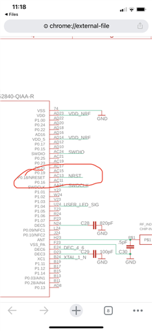
  • By reset mode I meant flipping the nreset pin which can be seen on our schematic. I attached a screenshot highlighting it.


    I am using the base blinky program. I wonder there is a hard fault. Maybe it’s the board configuration but I’m pretty sure I left most aliases the same so it would be compatible with the demo blinky out of the box  ( ex: left led 0 with the same name but changed the pin to match our board) 

  • Ah, so you mean that you can "debug" when reset is asserted (held low)? At that point the CPU is not running, though (and in fact most of the IC is in an undefined state while the reset pin is asserted).

    hmahdi said:
    I am using the base blinky program. I wonder there is a hard fault.

    Yes, it looks like it. Can you upload the full project including any modifications you have done so that I can take a look (in your previous upload I saw the board file etc but not the blinky project etc)? It could also make sense to remove your board specific code just for simplicity to try to narrow down the issue.

Related