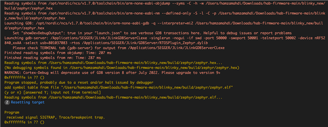
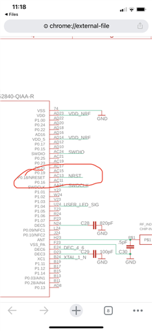
I have designed a custom board for the nrf52840 and upon testing it in the nrf connect sdk (using a JLink), I can only see the board when it's in bootloader mode. When it's in normal operation, the debugger does not show it.
Additionally, it does not appear as a USB device although I enabled USB CDC. In fact, I kept the configuration pretty much similar to the nrf52840 dongle when I defined the custom board on the nrf connect sdk.
Has anyone run into a similar issue? Are there any guidelines for how to debug such a problem?