
Hello!
We have a problem with setting up the radio on the nrf52840 to receive a special kind of packet that we are interested in. This packet is generated from an development master that is running a newly publish industrial communication protocol called IO-Link Wireless. IO-Link Wireless is similar and builds upon Bluetooth version 4.2 (Bluetooth Low Energy). What we want to do is to capture a configuration packet that can only be picked up at 2401 MHz or 2480 MHz.
Sofware wise we are using this https://developer.nordicsemi.com/nRF_Connect_SDK/doc/latest/nrf/samples/peripheral/radio_test/README.html radio sample to configure and mod the radio.
What we have done for now is what you can see in this picture.
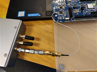
In the picture you can see the development master to the left, hooked up to 3 10 db attenuators and to that, a male to male converter hooked up to a wire that goes to the u.FL slot on the nrf52840. Initially the master had 3 antennas, we identified that one seems to be more operational then the other and therefore we removed that one and hooked it up this way.
We have done this to minimize interference and to try to monitor everything that is being sent out from the master. We are not sure if this setup is working and what the difference is between an external and internal antenna on the nrf52840 (if there even is one).
We also dont know if the radio sample that we are using is picking up these packets that the master is sending out, we know that the master is sending out a bunch of stuff but we are unsure if these packets are ending up on the u.FL slot, if they are, they are most certainly discarded by the radio infrastructure within the nrf52840 since its designed for BLE packets and NOT IO-Link wireless packets. Down below a picture of the radio modules within the nrf52840 is shown, taken from the specification of the board on page 311.
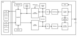
As you can see in the model of the radio, there is a lot of processes that happens to a received packet before it ends up in the ram, so receiving a IO-Link Wireless packet there is a longshot. However the packet that we are hunting after have the following structure:
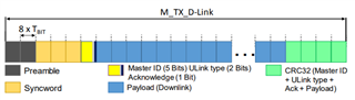
This is what is called a configuration downlink within the IO-Link Wireless literature it is used in for scanning nearby slaves, it ONLY occurs on 2401 and 2480 as mentioned. As you can see it has two bytes preamble which can either be 0x55 or 0xAA (similarly to BLE 2Mbit) depending on the first bit of the syncword. So if the first bit of the syncword is "0" we will have a 0xAAAA preamble and if its "1" we will have a 0x5555 preamble. When it comes to the configuration downlink we know that it has a certain syncword called "configsyncword" which will always be 0x3E9459 declared in the specification (we dont know why). We know that this particular masterID is 0x28. We suspect that the payload will be completely empty since this downlink is just for configuration purposes.
Now, we need help to configure/mod the radio sample that we are using so that we will be able to pick this up and make it not discard these packets, and we also want to understand where in the code it will end up, if we receive it. When running the sample we can navigate the radio with a shell which gives you the option to print rx, which shows the payload and number of packets received. If the radio is just right, it might be possible that the downlink shows up there but it is probably a longshot.
If we manage to do this, we can also sweep over all frequency within the 2.4 GHz band to eventually pick up other packets from the master, since IO-Link wireless uses frequency hopping it will send packages on different frequencys, and we might get lucky to catch some of them.
