Low Power Mode example not working

Hi,

I've been playing around with the attached low power mode example.  It seems to be written around the nRF SDK, but I am attempting to build and flash from within VSC using the NRF Connect SDK and Zephyr RTOS.  Not sure if this is part of my issue (I'm a bit of a novice at this stage).

End goal is to modify my own project code so that it:

  • Enters a RAM retention low power state when not doing anything
  • Exits this stage when I get a positive edge trigger on one of three different GPIO
  • Determine which GPIO caused the device to come out of low power mode, increment an appropriate counter, then go back into the low power mode.

This example sort of looks like it should do that, but there's a fair bit going on in retention.c/.h that I don't really follow.

Anyway, when I program my nRF52-DK with the code as is, it seems to step through things correctly, and I can see the impact on the current drain on my DK.  But in the final step, where its supposed to go into, something goes wrong and it skips past that and into the printk("ERROR: System off failed\n"); statement.

This is the output from the UART:
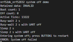
Any ideas why that call to pm_power_state_force(0u, (struct pm_state_info){PM_STATE_SOFT_OFF, 0, 0}); isn't working?
The other question I have is how do I check which GPIO caused the device to come out of low power state (when I can actually get that part working) so that I can increment the appropriate counter?  I'm assuming there is some sort of interrupt register for the two GPIO ports that I can somehow do a test on?
Cheers,
Mike
  • Hi

    First off, have you checked out the nRF5x System Off demo documentation pages? It should indeed be possible to use for putting the device to system OFF, with the possibility to demonstrate RAM retention by setting CONFIG_APP_RETENTION=y in your prj.conf file.

    One reason you might see the system OFF failing, is that you're running the application in debug mode, which won't actually put the device into system OFF, and is really the only thing coming to mind as to why the power_state_force() function would fail, unless you're also running some high priority tasks, which it doesn't seem like you do. For me to recreate this with the project you uploaded, can you please let me know what version of the nRF Connect SDK you're working on?

    Best regards,

    Simon

  • Hi Simon,

    Yep, read through those pages.  I can understand how the code in main.c is functioning, but the stuff in retention.c is a bit beyond me at this stage.  But first, I just want to get the demo code working.

    I had a look at my build settings and also in proj.config, and I can't see anywhere there where I've set up things to run in debug mode.

    FYI, my set up is:

    VSC - 1.66.1

    nRF Connect SDK - 1.9.1

    Zephyr - v2.7.99-ncs1-1

    Cheers,

    Mike

  • Hi Mike

    I tested this on my end, and I also saw the same behavior as you, it seems there's a line missing in the 1.9.1 version of this project. If you check out the latest version of this sample in the Zephyr project Github you can see that there's an additional line to actually put the board to sleep after the pm_power_state_force() function. 

    Please try adding the following line between pm_power_state_force() and the last printk() in the main loop.

    k_sleep(K_SECONDS(SLEEP_S));

    The next version of the nRF Connect SDK will also add this to the sample to make it run correctly.

    Best regards,

    Simon

  • Hi Simon,

    BINGO!  That fixed it.  I assume it needs a bit of time to get itself sorted before it can go into OFF mode, hence why the k_sleep() call is needed?

    The example uses Button 1 to kick it out of OFF mode.  It was easy enough for me to add Button 2 also as a mechanism to get it to come out of OFF, so I am assuming any GPIO that is enabled prior to going into OFF will trigger it out of that mode - is that correct?  Or is there somewhere I specifically have to add a CONFIG (or similar) statement to enable the "trigger out of OFF with GPIO" functionality?

    The other thing I want to be able to do is determine which GPIO has actually triggered the exit from OFF mode.  Ultimately there will be about 4 different GPIO I will want to have this functionality, and I'd like to be able to do something slightly different depending upon which GPIO caused the "reboot".  I'm assuming there is an interrupt status register for all the various GPIO that I could potentially check at first boot up?

    Regards,

    Mike

  • Calling the k_sleep(); function here will let the idle thread run and the PM subsystem will use the forced state.

    Any configured GPIO will be able to wake the device up when it is in system OFF indeed.

    Yes, there is a register called LATCH in the nRF52832, that indicates what GPIO have met a criteria set in the PIN_CNF[n].SENSE registers that you can check after the device has been woken up.

    Best regards,

    Simon

Related