Low Power Mode example not working

Hi,

I've been playing around with the attached low power mode example.  It seems to be written around the nRF SDK, but I am attempting to build and flash from within VSC using the NRF Connect SDK and Zephyr RTOS.  Not sure if this is part of my issue (I'm a bit of a novice at this stage).

End goal is to modify my own project code so that it:

  • Enters a RAM retention low power state when not doing anything
  • Exits this stage when I get a positive edge trigger on one of three different GPIO
  • Determine which GPIO caused the device to come out of low power mode, increment an appropriate counter, then go back into the low power mode.

This example sort of looks like it should do that, but there's a fair bit going on in retention.c/.h that I don't really follow.

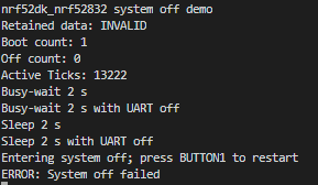
Anyway, when I program my nRF52-DK with the code as is, it seems to step through things correctly, and I can see the impact on the current drain on my DK.  But in the final step, where its supposed to go into, something goes wrong and it skips past that and into the printk("ERROR: System off failed\n"); statement.

This is the output from the UART:

Any ideas why that call to pm_power_state_force(0u, (struct pm_state_info){PM_STATE_SOFT_OFF, 0, 0}); isn't working?
The other question I have is how do I check which GPIO caused the device to come out of low power state (when I can actually get that part working) so that I can increment the appropriate counter?  I'm assuming there is some sort of interrupt register for the two GPIO ports that I can somehow do a test on?
Cheers,
Mike
Parents
  • Calling the k_sleep(); function here will let the idle thread run and the PM subsystem will use the forced state.

    Any configured GPIO will be able to wake the device up when it is in system OFF indeed.

    Yes, there is a register called LATCH in the nRF52832, that indicates what GPIO have met a criteria set in the PIN_CNF[n].SENSE registers that you can check after the device has been woken up.

    Best regards,

    Simon

Reply
  • Calling the k_sleep(); function here will let the idle thread run and the PM subsystem will use the forced state.

    Any configured GPIO will be able to wake the device up when it is in system OFF indeed.

    Yes, there is a register called LATCH in the nRF52832, that indicates what GPIO have met a criteria set in the PIN_CNF[n].SENSE registers that you can check after the device has been woken up.

    Best regards,

    Simon

Children
No Data
Related