This discussion has been locked.
You can no longer post new replies to this discussion. If you have a question you can start a new discussion

aQFN Footprint Blind Vias

Hi,

I am designing a PCB including the nRF52833, and I just wanted to confirm the requirements for the vias-in-pad for the signals on the inner row of the aQFN footprint.

Is it okay to make any of these through-hole vias instead of blind, as long as they are still capped and have the correct dimensions of 0.15 mm hole/0.25 mm pad?

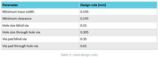
I saw that Table 3 in the nAN-40 app note states much larger dimensions for through-hole vias, seemingly in reference to the vias-in-pad.  Just wanted to make sure I fully understood why blind vias were being used before I deviated from the reference design.

Thanks a lot for your help.

  • Hi,

    Note: just want to inform you that we do HW reviews, so you can request a review of the design here on Devzone. Simply create a new case, include the schematic and layout files, PDF/GERBER or Altium files and we will provide feedback.  


    Is the plan to use only some of the pins with through-hole or all?

    Using blind VIAS does not innfetere with all other layers, so for example if the centre pad grounding is poor and it is disrupted by through-hole vias that cut of the centre pad from the rest of the ground plane. 


    So, we always recommend that you follow the latest ref design we have: nRF52833 SoC - Downloads - nordicsemi.com 

    Regards,
    Jonathan

  • Hi Jonathan,

    Thanks for the reply.  The plan is to use vias-in pad for just a few of the pads on the inner row of the aQFN footprint.  In the reference design, they are blind vias, but I was hoping to make them through-hole to potentially reduce cost.  I don't have any issues with them interfering with objects on the other layers.

    They will have the same pad diameter and hole diameter as the blind vias in the reference design, still capped, but will be through-hole.  Just wanted to make sure there wouldn't be a problem with that.

    Justin

  • Just wanted to make sure I fully understood why blind vias were being used before I deviated from the reference design.

    Due to manufactures have limitations and prefers standard layouts to have micro via aspect ratio 1x1(usually), through hole vias needs to be larger due to the fact that they are drilled and need to be caped. Capping of small through hole is often not recommend do to trapping air in the via, this can cause expiation wit temp and atmosphere pressure changes. 

    Manufacturer limitations or etiquette you could say is part of the reason. So contact the manufacturer and see if it will be cheaper, might not. 

    Regards,
    Jonathan

Related