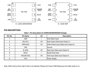
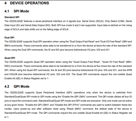
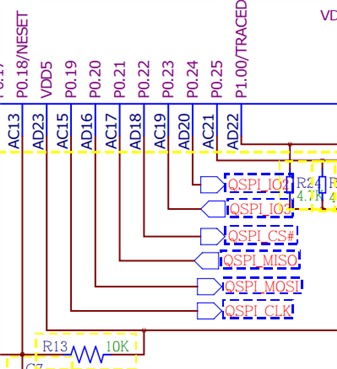
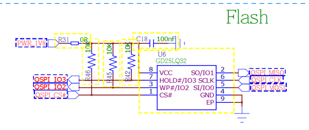
NCS read flash GD25LQ32EEIGR

Hi,

NCS1.9.1, VSCode, nRF52840
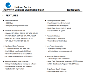
i want to read flash GD25LQ32EEIGR,using qspi_flash (that in  \v1.9.1\zephyr\tests\boards\altera_max10\qspi)
#define MAX_NUM_OF_SECTORS		1024
#define NUM_OF_SECTORS_TO_TEST		4
#define FLASH_SECTOR_SIZE		65536
#define TEST_DATA_LEN			4

void test_qspi_flash(void)
{
	const struct device *flash_dev;
	uint32_t i, offset, rd_val, wr_val;
	uint8_t wr_buf[4] = {0xAA, 0xBB, 0xCC, 0xDD};
	uint8_t rd_buf[2];

	#define CONFIG_SOC_FLASH_NIOS2_QSPI_DEV_NAME "QSPI"

	flash_dev = device_get_binding(CONFIG_SOC_FLASH_NIOS2_QSPI_DEV_NAME);
	zassert_equal(!flash_dev, TC_PASS, "Flash device not found!");

	for (i = 0U; i < NUM_OF_SECTORS_TO_TEST; i++) {
		TC_PRINT("\nTesting: Flash Sector-%d\n", i);
		offset = FLASH_SECTOR_SIZE * i;

		/* Flash Erase Test */
		TC_PRINT("	Flash Erase Test...");
		zassert_equal(flash_erase(flash_dev,
				offset, FLASH_SECTOR_SIZE),
				TC_PASS, "Flash erase call failed!");
		zassert_equal(flash_read(flash_dev, offset,
				&rd_val, TEST_DATA_LEN),
				TC_PASS, "Flash read call failed!");
		/* In case of erase all bits will be set to 1 */
		wr_val = 0xffffffff;
		zassert_equal(rd_val != wr_val,	TC_PASS,
					"Flash Erase Test failed!!");
		TC_PRINT("PASS\n");


		/* Flash Write & Read Test */
		TC_PRINT("	Flash Write & Read Test...");
		wr_val = 0xAABBCCDD;
		zassert_equal(flash_write(flash_dev, offset,
				&wr_val, TEST_DATA_LEN),
				TC_PASS, "Flash write call failed!");
		zassert_equal(flash_read(flash_dev, offset,
				&rd_val, TEST_DATA_LEN),
				TC_PASS, "Flash read call failed!");
		zassert_equal(rd_val != wr_val,	TC_PASS,
					"Flash Write & Read Test failed!!");
		TC_PRINT("PASS\n");


		/* Flash Unaligned Read Test */
		TC_PRINT("	Flash Unaligned Read Test...");
		zassert_equal(flash_write(flash_dev, offset + sizeof(wr_val),
				&wr_buf, sizeof(wr_buf)),
				TC_PASS, "Flash write call failed!");
		zassert_equal(flash_read(flash_dev, offset + sizeof(wr_val) + 1,
				&rd_buf, sizeof(rd_buf)),
				TC_PASS, "Flash read call failed!");
		zassert_equal(memcmp(wr_buf + 1, rd_buf, sizeof(rd_buf)),
				TC_PASS, "Flash Write & Read Test failed!!");
		TC_PRINT("PASS\n");
	}
}
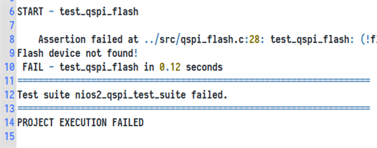
log:flash devece not found!
&qspi {
        compatible = "nordic,nrf-qspi";
        #address-cells = < 0x1 >;
        #size-cells = < 0x0 >;
        status = "okay";
        label = "QSPI";
    	sck-pin = < 0x13 >;
    	io-pins = < 0x15 >, < 0x14 >, < 0x18 >, < 0x17 >;// MISO=IO0  MOSI=IO1  IO2  IO3
    	csn-pins = < 0x16 >;

        GD25LQ32E: GD25LQ32E_@0 {
                compatible = "nordic,qspi-nor";
                reg = < 0x0 >;
                writeoc = "pp4io";
                readoc = "read4io";
                sck-frequency = < 0x7a1200 >;
                label = "GD25LQ32EEIGR";
                jedec-id = [ C2 28 17 ];
                sfdp-bfp = [ E5 20 F1 FF FF FF FF 03 44 EB 08 6B 08 3B 04 BB EE FF FF FF FF FF 00 FF FF FF 00 FF 0C 20 0F 52 10 D8 00 FF 23 72 F5 00 82 ED 04 CC 44 83 68 44 30 B0 30 B0 F7 C4 D5 5C 00 BE 29 FF F0 D0 FF FF ];
                size = < 0x4000000 >;
                has-dpd;
                t-enter-dpd = < 0x2710 >;
                t-exit-dpd = < 0x88b8 >;
        };
};
i don't know how to write overlay file,
                writeoc = "pp4io";
                readoc = "read4io";
                sck-frequency = < 0x7a1200 >;
                label = "GD25LQ32EEIGR";
                jedec-id = [ C2 28 17 ];
                sfdp-bfp = [ E5 20 F1 FF FF FF FF 03 44 EB 08 6B 08 3B 04 BB EE FF FF FF FF FF 00 FF FF FF 00 FF 0C 20 0F 52 10 D8 00 FF 23 72 F5 00 82 ED 04 CC 44 83 68 44 30 B0 30 B0 F7 C4 D5 5C 00 BE 29 FF F0 D0 FF FF ];
                size = < 0x4000000 >;
                has-dpd;
                t-enter-dpd = < 0x2710 >;
                t-exit-dpd
I don't know the meaning of the blue words,
  
Best Regards
Parents
  • Can you take a look at this this case, which I think is somewhat similiar but with another qpsi flash device:
    https://devzone.nordicsemi.com/f/nordic-q-a/85983/qspi-flash-sample-project-error/

    The data in blue as specific for the flash device, so just keep them as-is. 

    Kenneth

  • Hi,

    thanks for reply, wo read your link.

    i can runing with mx25r64 flash on DK,it's work well.

    but change to GD25LQ32EEIGR,log:flash devece not found!

    &qspi {
    	compatible = "nordic,nrf-qspi";
    	#address-cells = < 0x1 >;
    	#size-cells = < 0x0 >;
    	reg = < 0x40029000 0x1000 >, < 0x12000000 0x8000000 >;
    	reg-names = "qspi", "qspi_mm";
    	interrupts = < 0x29 0x1 >;
    	status = "okay";
    	label = "QSPI";
    	sck-pin = < 0x13 >;
    	io-pins = < 0x14 >, < 0x15 >, < 0x16 >, < 0x17 >;// MISO=IO0  MOSI=IO1  IO2  IO3
    	csn-pins = < 0x11 >;	// CS#
    
    	mx25r64: mx25r6435f@0 {
    		compatible = "nordic,qspi-nor";
    		reg = < 0x0 >;
    		writeoc = "pp4io";
    		readoc = "read4io";
    		sck-frequency = < 0x7a1200 >;
    		label = "MA25R64"; //   GD25LQ32E
    		jedec-id = [ C2 28 17 ];
    		sfdp-bfp = [ E5 20 F1 FF FF FF FF 03 44 EB 08 6B 08 3B 04 BB EE FF FF FF FF FF 00 FF FF FF 00 FF 0C 20 0F 52 10 D8 00 FF 23 72 F5 00 82 ED 04 CC 44 83 68 44 30 B0 30 B0 F7 C4 D5 5C 00 BE 29 FF F0 D0 FF FF ];
    		size = < 0x4000000 >;
    		has-dpd;
    		t-enter-dpd = < 0x2710 >;
    		t-exit-dpd = < 0x88b8 >;
    	};
    };


    Best Regards

  • Can you try this one? You likely need to change the overlay file to work with your board.

    3513.qspi.zip

  • Hello,Kenneth,

    thanks for your reply.

    i' have change the pin in overlay file.

    &uart0 {
    	status = "okay";
    	label = "UART_0";
    	current-speed = < 0x1c200 >;
    	tx-pin = < 0x08 >;
    	rx-pin = < 0x28 >;
    	rx-pull-up;
    	rts-pin = < 0xFFFFFFFF >;
    	cts-pin = < 0xFFFFFFFF >;
    };
    &uart1 {
    	status = "disabled";
    	label = "UART_1";
    };
    &spi2 {
    	status = "disabled";
    	label = "UART_1";
    };
    &egu2 {
    	status = "disabled";
    };
    &egu3 {
    	status = "disabled";
    };
    &egu4 {
    	status = "disabled";
    };
    
    
    &qspi {
    	status = "okay";
    	sck-pin = < 0x13 >;
    	io-pins = < 0x15 >, < 0x14 >, < 0x18 >, < 0x17 >;// MISO=IO0  MOSI=IO1  IO2  IO3
    	csn-pins = < 0x16 >;
    
    	GD25LQ32E: GD25LQ32E_@0 {
    		compatible = "nordic,qspi-nor";
    		reg = < 0x0 >;
    		writeoc = "pp4io";
    		readoc = "read4io";
    		sck-frequency = < 0x7a1200 >;
    		label = "GD25LQ32EEIGR";
    		jedec-id = [ C2 28 17 ];
    		sfdp-bfp = [ E5 20 F1 FF FF FF FF 03 44 EB 08 6B 08 3B 04 BB EE FF FF FF FF FF 00 FF FF FF 00 FF 0C 20 0F 52 10 D8 00 FF 23 72 F5 00 82 ED 04 CC 44 83 68 44 30 B0 30 B0 F7 C4 D5 5C 00 BE 29 FF F0 D0 FF FF ];
    		size = < 0x4000000 >;
    		has-dpd;
    		t-enter-dpd = < 0x2710 >;
    		t-exit-dpd = < 0x88b8 >;
    	};
    };

    the pin PWR_1V8  voltage is 1.8V.(Measure with a multimeter)


    Best Regards

Reply
  • Hello,Kenneth,

    thanks for your reply.

    i' have change the pin in overlay file.

    &uart0 {
    	status = "okay";
    	label = "UART_0";
    	current-speed = < 0x1c200 >;
    	tx-pin = < 0x08 >;
    	rx-pin = < 0x28 >;
    	rx-pull-up;
    	rts-pin = < 0xFFFFFFFF >;
    	cts-pin = < 0xFFFFFFFF >;
    };
    &uart1 {
    	status = "disabled";
    	label = "UART_1";
    };
    &spi2 {
    	status = "disabled";
    	label = "UART_1";
    };
    &egu2 {
    	status = "disabled";
    };
    &egu3 {
    	status = "disabled";
    };
    &egu4 {
    	status = "disabled";
    };
    
    
    &qspi {
    	status = "okay";
    	sck-pin = < 0x13 >;
    	io-pins = < 0x15 >, < 0x14 >, < 0x18 >, < 0x17 >;// MISO=IO0  MOSI=IO1  IO2  IO3
    	csn-pins = < 0x16 >;
    
    	GD25LQ32E: GD25LQ32E_@0 {
    		compatible = "nordic,qspi-nor";
    		reg = < 0x0 >;
    		writeoc = "pp4io";
    		readoc = "read4io";
    		sck-frequency = < 0x7a1200 >;
    		label = "GD25LQ32EEIGR";
    		jedec-id = [ C2 28 17 ];
    		sfdp-bfp = [ E5 20 F1 FF FF FF FF 03 44 EB 08 6B 08 3B 04 BB EE FF FF FF FF FF 00 FF FF FF 00 FF 0C 20 0F 52 10 D8 00 FF 23 72 F5 00 82 ED 04 CC 44 83 68 44 30 B0 30 B0 F7 C4 D5 5C 00 BE 29 FF F0 D0 FF FF ];
    		size = < 0x4000000 >;
    		has-dpd;
    		t-enter-dpd = < 0x2710 >;
    		t-exit-dpd = < 0x88b8 >;
    	};
    };

    the pin PWR_1V8  voltage is 1.8V.(Measure with a multimeter)


    Best Regards

Children
Related