This discussion has been locked.
You can no longer post new replies to this discussion. If you have a question you can start a new discussion

Issue with updating nRF52832 over USART

 I am using an STM32L4 chip that sends an update to the nRF52832 on a ublox module over USART. I assume the nordic chip is in the bootloader during the update.

We get a UART error: 4 and when we observe the UART lines we see that on the TX line of the nRF the stop bit is not present. I assume the nRF does not pull the line high properly after transmitting a frame. (we do not use pull-up resistors on the USART lines on STM32L4 side)

When trying to update with an OTA the device updates but then falls back into the bootloader at startup making me assume the problem is with the bootloader.


I am wondering if there is such documented cases of bootloader errors or if the missing stop bit could point to another issue with my HW/SW?

Thank you for any hint!

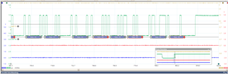
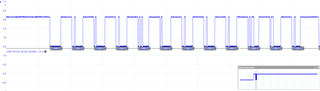
Bad behavior with missing stop bit:

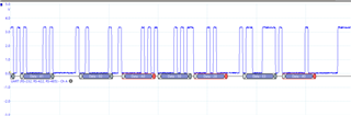
Good behavior with stop bit present:

Bad behavior with 

  • blue: CTS

  • red: RTS

  • green: UART RX

  • yellow: UART TX

  • We get a UART error: 4 and when we observe the UART lines we see that on the TX line of the nRF the stop bit is not present. I assume the nRF does not pull the line high properly after transmitting a frame. (we do not use pull-up resistors on the USART lines on STM32L4 side)

    This UART error:4, is it on the nRF end or the STM end? UART on nrf52832 is quite mature peripheral and I do not suspect that there is an hardware issue with it.

    There probably is a configuration issue with the pullup on the nRF side or the STM side.

    Can you show some code snippets on how you are configuring the pins on the UART on nRF side?.

  • This is the configuration on STML4 side:

    void MX_USART2_UART_Init(void)
    {
    
      huart2.Instance = USART2;
      huart2.Init.BaudRate = 921600;
      huart2.Init.WordLength = UART_WORDLENGTH_8B;
      huart2.Init.StopBits = UART_STOPBITS_1;
      huart2.Init.Parity = UART_PARITY_NONE;
      huart2.Init.Mode = UART_MODE_TX_RX;
      huart2.Init.HwFlowCtl = UART_HWCONTROL_RTS_CTS;
      huart2.Init.OverSampling = UART_OVERSAMPLING_16;
      huart2.Init.OneBitSampling = UART_ONE_BIT_SAMPLE_ENABLE;
      huart2.Init.ClockPrescaler = UART_PRESCALER_DIV1;
      huart2.AdvancedInit.AdvFeatureInit = UART_ADVFEATURE_NO_INIT;
      if (HAL_UART_Init(&huart2) != HAL_OK)
      {
        Error_Handler();
      }
      if (HAL_UARTEx_SetTxFifoThreshold(&huart2, UART_TXFIFO_THRESHOLD_3_4) != HAL_OK)
      {
        Error_Handler();
      }
      if (HAL_UARTEx_SetRxFifoThreshold(&huart2, UART_RXFIFO_THRESHOLD_3_4) != HAL_OK)
      {
        Error_Handler();
      }
      if (HAL_UARTEx_EnableFifoMode(&huart2) != HAL_OK)
      {
        Error_Handler();
      }
    
    }

      else if(uartHandle->Instance==USART2)
      {
      /* USER CODE BEGIN USART2_MspInit 0 */
    
      /* USER CODE END USART2_MspInit 0 */
        /* USART2 clock enable */
        __HAL_RCC_USART2_CLK_ENABLE();
    
        __HAL_RCC_GPIOD_CLK_ENABLE();
        /**USART2 GPIO Configuration
        PD5     ------> USART2_TX
        PD6     ------> USART2_RX
        PD3     ------> USART2_CTS
        PD4     ------> USART2_RTS
        */
        GPIO_InitStruct.Pin = GPIO_PIN_5|GPIO_PIN_6|GPIO_PIN_3|GPIO_PIN_4;
        GPIO_InitStruct.Mode = GPIO_MODE_AF_PP;
        GPIO_InitStruct.Pull = GPIO_NOPULL;
        GPIO_InitStruct.Speed = GPIO_SPEED_FREQ_VERY_HIGH;
        GPIO_InitStruct.Alternate = GPIO_AF7_USART2;
        HAL_GPIO_Init(GPIOD, &GPIO_InitStruct);
    
        /* USART2 DMA Init */
        /* USART2_RX Init */
        hdma_usart2_rx.Instance = DMA2_Stream0;
        hdma_usart2_rx.Init.Request = DMA_REQUEST_USART2_RX;
        hdma_usart2_rx.Init.Direction = DMA_PERIPH_TO_MEMORY;
        hdma_usart2_rx.Init.PeriphInc = DMA_PINC_DISABLE;
        hdma_usart2_rx.Init.MemInc = DMA_MINC_ENABLE;
        hdma_usart2_rx.Init.PeriphDataAlignment = DMA_PDATAALIGN_BYTE;
        hdma_usart2_rx.Init.MemDataAlignment = DMA_MDATAALIGN_BYTE;
        hdma_usart2_rx.Init.Mode = DMA_NORMAL;
        hdma_usart2_rx.Init.Priority = DMA_PRIORITY_HIGH;
        hdma_usart2_rx.Init.FIFOMode = DMA_FIFOMODE_DISABLE; /***@note should be disabled, could be problematic with the RTO feature of the UART Rx  */
        hdma_usart2_rx.Init.FIFOThreshold = DMA_FIFO_THRESHOLD_HALFFULL;
        hdma_usart2_rx.Init.MemBurst = DMA_MBURST_SINGLE;
        hdma_usart2_rx.Init.PeriphBurst = DMA_PBURST_SINGLE;
        if (HAL_DMA_Init(&hdma_usart2_rx) != HAL_OK)
        {
          Error_Handler();
        }
    
        __HAL_LINKDMA(uartHandle,hdmarx,hdma_usart2_rx);
    
        /* USART2_TX Init */
        hdma_usart2_tx.Instance = DMA2_Stream1;
        hdma_usart2_tx.Init.Request = DMA_REQUEST_USART2_TX;
        hdma_usart2_tx.Init.Direction = DMA_MEMORY_TO_PERIPH;
        hdma_usart2_tx.Init.PeriphInc = DMA_PINC_DISABLE;
        hdma_usart2_tx.Init.MemInc = DMA_MINC_ENABLE;
        hdma_usart2_tx.Init.PeriphDataAlignment = DMA_PDATAALIGN_BYTE;
        hdma_usart2_tx.Init.MemDataAlignment = DMA_MDATAALIGN_BYTE;
        hdma_usart2_tx.Init.Mode = DMA_NORMAL;
        hdma_usart2_tx.Init.Priority = DMA_PRIORITY_LOW;
        hdma_usart2_tx.Init.FIFOMode = DMA_FIFOMODE_ENABLE;
        hdma_usart2_tx.Init.FIFOThreshold = DMA_FIFO_THRESHOLD_HALFFULL;
        hdma_usart2_tx.Init.MemBurst = DMA_MBURST_SINGLE;
        hdma_usart2_tx.Init.PeriphBurst = DMA_PBURST_SINGLE;
        if (HAL_DMA_Init(&hdma_usart2_tx) != HAL_OK)
        {
          Error_Handler();
        }
    
        __HAL_LINKDMA(uartHandle,hdmatx,hdma_usart2_tx);
    
        /* USART2 interrupt Init */
        HAL_NVIC_SetPriority(USART2_IRQn, 6, 0);
        HAL_NVIC_EnableIRQ(USART2_IRQn);
      /* USER CODE BEGIN USART2_MspInit 1 */
        HAL_NVIC_SetPriority(USART2_IRQn, ISR_PRIO_USART2, 0);
      /* USER CODE END USART2_MspInit 1 */

    void HAL_MspInit(void)
    {
      /* USER CODE BEGIN MspInit 0 */
    
      /* USER CODE END MspInit 0 */
    
      __HAL_RCC_SYSCFG_CLK_ENABLE();
    
      /* System interrupt init*/
      /* MemoryManagement_IRQn interrupt configuration */
    //  HAL_NVIC_SetPriority(MemoryManagement_IRQn, 5, 0);
    //  /* BusFault_IRQn interrupt configuration */
    //  HAL_NVIC_SetPriority(BusFault_IRQn, 5, 0);
    //  /* UsageFault_IRQn interrupt configuration */
    //  HAL_NVIC_SetPriority(UsageFault_IRQn, 5, 0);
    //  /* SVCall_IRQn interrupt configuration */
    //  HAL_NVIC_SetPriority(SVCall_IRQn, 5, 0);
    //  /* DebugMonitor_IRQn interrupt configuration */
    //  HAL_NVIC_SetPriority(DebugMonitor_IRQn, 5, 0);
    //  /* PendSV_IRQn interrupt configuration */
    //  HAL_NVIC_SetPriority(PendSV_IRQn, 15, 0);
    
      /* USER CODE BEGIN MspInit 1 */
    
      /* USER CODE END MspInit 1 */
    }

    And on nRF32 side:

    #ifndef NRFX_UARTE_ENABLED
    #define NRFX_UARTE_ENABLED 1
    #endif
    // <o> NRFX_UARTE0_ENABLED - Enable UARTE0 instance
    #ifndef NRFX_UARTE0_ENABLED
    #define NRFX_UARTE0_ENABLED 0
    #endif
    
    // <o> NRFX_UARTE_DEFAULT_CONFIG_HWFC  - Hardware Flow Control
    
    // <0=> Disabled
    // <1=> Enabled
    
    #ifndef NRFX_UARTE_DEFAULT_CONFIG_HWFC
    #define NRFX_UARTE_DEFAULT_CONFIG_HWFC 0
    #endif
    
    // <o> NRFX_UARTE_DEFAULT_CONFIG_PARITY  - Parity
    
    // <0=> Excluded
    // <14=> Included
    
    #ifndef NRFX_UARTE_DEFAULT_CONFIG_PARITY
    #define NRFX_UARTE_DEFAULT_CONFIG_PARITY 0
    #endif
    
    // <o> NRFX_UARTE_DEFAULT_CONFIG_BAUDRATE  - Default Baudrate
    
    // <323584=> 1200 baud
    // <643072=> 2400 baud
    // <1290240=> 4800 baud
    // <2576384=> 9600 baud
    // <3862528=> 14400 baud
    // <5152768=> 19200 baud
    // <7716864=> 28800 baud
    // <8388608=> 31250 baud
    // <10289152=> 38400 baud
    // <15007744=> 56000 baud
    // <15400960=> 57600 baud
    // <20615168=> 76800 baud
    // <30801920=> 115200 baud
    // <61865984=> 230400 baud
    // <67108864=> 250000 baud
    // <121634816=> 460800 baud
    // <251658240=> 921600 baud
    // <268435456=> 1000000 baud
    
    #ifndef NRFX_UARTE_DEFAULT_CONFIG_BAUDRATE
    #define NRFX_UARTE_DEFAULT_CONFIG_BAUDRATE 251658240
    #endif
    
    // <o> NRFX_UARTE_DEFAULT_CONFIG_IRQ_PRIORITY  - Interrupt priority
    
    // <0=> 0 (highest)
    // <1=> 1
    // <2=> 2
    // <3=> 3
    // <4=> 4
    // <5=> 5
    // <6=> 6
    // <7=> 7
    
    #ifndef NRFX_UARTE_DEFAULT_CONFIG_IRQ_PRIORITY
    #define NRFX_UARTE_DEFAULT_CONFIG_IRQ_PRIORITY 6
    #endif

    in makefile:

      $(SDK_ROOT)/components/libraries/bootloader/serial_dfu/nrf_dfu_serial.c \
      $(SDK_ROOT)/integration/nrfx/legacy/nrf_drv_uart.c \
      $(SDK_ROOT)/modules/nrfx/drivers/src/nrfx_uart.c \
      $(SDK_ROOT)/modules/nrfx/drivers/src/nrfx_uarte.c \
      $(SDK_ROOT)/modules/nrfx/drivers/src/prs/nrfx_prs.c
    #  $(SDK_ROOT)/components/libraries/bootloader/serial_dfu/nrf_dfu_serial_uart.c \
      
    INC_FOLDERS += \
      $(SDK_ROOT)/integration/nrfx/legacy \
      $(SDK_ROOT)/modules/nrfx/drivers/include \

    --> What I also noticed is that in the above measurements of UART the Stop bit is present, just not long enough. What might cause this? Maybe the unconventional UART frequency?

    --> The reason for the Hardware being suspicious is that the error only occurs sometimes and only on some devices

  • pressure_sensor_nonconn_adv said:
    --> What I also noticed is that in the above measurements of UART the Stop bit is present, just not long enough. What might cause this? Maybe the unconventional UART frequency?

    Can you try this with lower frequencies and sees if the behavior is the same. I have not heard of inadequate length of stop bit before.I am also not able to see any internal pull configuration on the pins if there are any. Have you setup pullup on the com pins from the SoC?

  • I will try with lower frequency values and enabling the pullup on RX and TX lines on STM32-side.

    I also found that the error only occurs at higher temperatures for which there are similar issues already:

    https://devzone.nordicsemi.com/f/nordic-q-a/22876/uart-heat-problem

    https://devzone.nordicsemi.com/f/nordic-q-a/52065/uart-frame-errors

    They propose to turn on the HFCLK for UART transmission with sd_clock_hfclk_request()

    I tried doing this but had no success. My clock configuration is the following:

    //==========================================================
    // <o> NRF_SDH_CLOCK_LF_SRC  - SoftDevice clock source.
     
    // <0=> NRF_CLOCK_LF_SRC_RC 
    // <1=> NRF_CLOCK_LF_SRC_XTAL 
    // <2=> NRF_CLOCK_LF_SRC_SYNTH 
    
    #ifndef NRF_SDH_CLOCK_LF_SRC
    #define NRF_SDH_CLOCK_LF_SRC 0//0 armando//1 original
    #endif
    
    // <o> NRF_SDH_CLOCK_LF_RC_CTIV - SoftDevice calibration timer interval. 
    #ifndef NRF_SDH_CLOCK_LF_RC_CTIV
    #define NRF_SDH_CLOCK_LF_RC_CTIV 16 //armando//0 original
    #endif
    
    // <o> NRF_SDH_CLOCK_LF_RC_TEMP_CTIV - SoftDevice calibration timer interval under constant temperature. 
    // <i> How often (in number of calibration intervals) the RC oscillator shall be calibrated
    // <i>  if the temperature has not changed.
    
    #ifndef NRF_SDH_CLOCK_LF_RC_TEMP_CTIV
    #define NRF_SDH_CLOCK_LF_RC_TEMP_CTIV 2 //armando //0 original
    #endif
    
    // <o> NRF_SDH_CLOCK_LF_ACCURACY  - External clock accuracy used in the LL to compute timing.
     
    // <0=> NRF_CLOCK_LF_ACCURACY_250_PPM 
    // <1=> NRF_CLOCK_LF_ACCURACY_500_PPM 
    // <2=> NRF_CLOCK_LF_ACCURACY_150_PPM 
    // <3=> NRF_CLOCK_LF_ACCURACY_100_PPM 
    // <4=> NRF_CLOCK_LF_ACCURACY_75_PPM 
    // <5=> NRF_CLOCK_LF_ACCURACY_50_PPM 
    // <6=> NRF_CLOCK_LF_ACCURACY_30_PPM 
    // <7=> NRF_CLOCK_LF_ACCURACY_20_PPM 
    // <8=> NRF_CLOCK_LF_ACCURACY_10_PPM 
    // <9=> NRF_CLOCK_LF_ACCURACY_5_PPM 
    // <10=> NRF_CLOCK_LF_ACCURACY_2_PPM 
    // <11=> NRF_CLOCK_LF_ACCURACY_1_PPM 
    
    #ifndef NRF_SDH_CLOCK_LF_ACCURACY
    #define NRF_SDH_CLOCK_LF_ACCURACY 1 // armando //7 original
    #endif

    --> I wondered if the above even makes sense since I am not using the softdevice (I am working with the bootloader). So do I need to use the NRF driver instead?

    #define NRF_CLOCK_ENABLED 1
    

  • UART uses HFCLK and the clock configuration you provided is for LFCLK. I do not think that the issue you are seeing is related to LFCLK. What is the accuracy of the XTAL HFCLK that you are are using? Check the specs to see the temperatures and accuracies that it supports.

    pressure_sensor_nonconn_adv said:
    They propose to turn on the HFCLK for UART transmission with sd_clock_hfclk_request()

    You need to call nrf_drv_clock_hfclk_request to start the XTAL and you can find this API in nRF5SDK\integration\nrfx\legacy\nrf_drv_clock.h

Related