Custom PCB with MDBT40

Hi there,

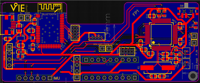
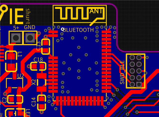
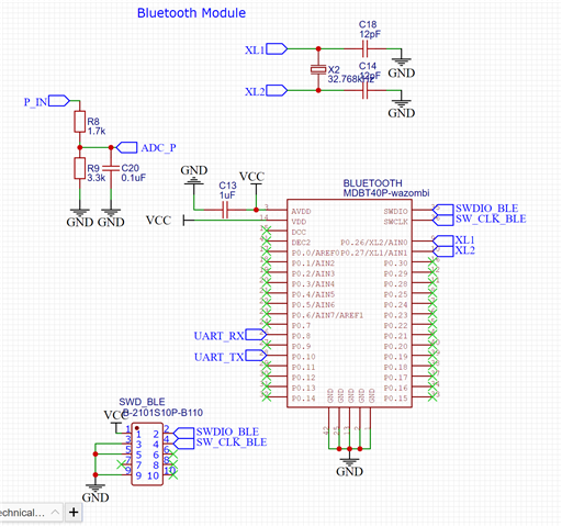
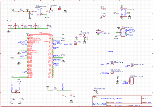
we are a student project and are using the nRF51822 Chip with the MDBT40 module. We designed our own custom PCB and followed the instructions for the circuit as well as the antenna. We already manufactured the PCB. Unfortunately something is wrong with it. When we connect our PCB via USB to the power supply, our voltage regulator gets very hot and somewhere a short develops. Our PCB functions perfectly if we don't solder the MDBT40 module so therefore we assume that the problem lies with the module or the modules circuit and not the rest of our PCB. We also solderd some cables to all used pins of the MDBT40 and connected them to our normal UART, VCC, GND debug pins of the board and everything worked fine. We tried to solve this problem with mulitple PCBs so we don't think the problem accurs due to a soldering short.

Can someone help us? Becuase we have no idea anymore what could cause this problem.

Thanks anyone so much in advance!

Parents
  • There's nothing wrong with the schematic or layout as far as I can see. Check of you have the correct voltage on the correct pins before you mount the module. The module shouldn't need more than VDD on two pins plus ground to operate. Check for solder issues as well. 

  • Thank you very much for your answer. So I checked the voltage before mounting the module. My VDD pins are 3.3V as well as the UART TX pin. All the other pins are low. Is that correct?

    I just mounted a new one and only soldered the two VDD and five ground pins. Befor connecting it to the power supply, I checked with a multimeter for a short. Non was found. As I connected the power supply the same happend as with the last ones: it got hot and "died". Afterwards I checked again for shorts and there was one between VDD and GND. After I removed the module kind of forcefully I could also see that there was no shortage between the pins on the backside of the module.

Reply
  • Thank you very much for your answer. So I checked the voltage before mounting the module. My VDD pins are 3.3V as well as the UART TX pin. All the other pins are low. Is that correct?

    I just mounted a new one and only soldered the two VDD and five ground pins. Befor connecting it to the power supply, I checked with a multimeter for a short. Non was found. As I connected the power supply the same happend as with the last ones: it got hot and "died". Afterwards I checked again for shorts and there was one between VDD and GND. After I removed the module kind of forcefully I could also see that there was no shortage between the pins on the backside of the module.

Children
Related