This discussion has been locked.
You can no longer post new replies to this discussion. If you have a question you can start a new discussion

AoA Basic IQ Validation

I've successfully built the 'direction_finding_connectionless_tx' project and flashed that to an nRF52833dk, and built the 'direction_finding_connectionless_rx' project with some changes and flashed that to another nRF52833dk connected to a Nordic PCA20054 12-patch antenna array board. I wasn't able to get an official PCA20054, so I built my own from the design files, which makes me suspicious of the data and wanting to do some basic validation before getting too complicated.

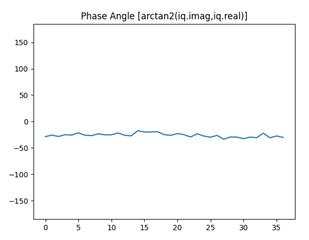
As a basic sanity check, if I limit the receiver to only scan on a single antenna, within a single CTE scan all the samples should have very similar IQ values if the transmitter and receiver are stationary right? I know that normally IQ values would change as the signal is modulated, but I thought that's part of what makes the CTE special since it is completely unmodulated giving a constant signal so the differences between different antennas could be compared.

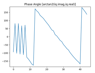
Plotting the phase angle over time from the IQ samples taken from a single antenna gives me the following graph:

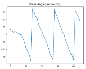
Amplitudes appear to remain relatively constant, but the phase angle is constantly falling and I'm not sure why. It appears to be falling at a relatively constant rate which feels like it might be a good thing, but if so I'm missing something.

Thanks for any insight!

  • Hi

    The AoA direction finding solution we provide will only output the raw IQ data by default, as we don't provide the AoA algorithm necessary to make use of the data collected by the antenna array. There is no point in looking at the raw data as it needs to be converted into vector form to review it properly. You can check out this page for information on the various formulas used to translate IQ data between polar and rectangular form. We've had multiple questions on this on the Devzone earlier. Please refer to the other threads where it has been discussed for more details.

    Best regards,

    Simon

  • So I think I figured at least this first hurdle out over the weekend, and what I was missing is that while the CTE signal is "unmodulated" it is mixed with a sine wave and part of the reason for the reference period is to calculate the phase velocity of that mixed signal so it can be subtracted from the rest of the sample to make them all appear incident on all antennas at the same moment.

    Also, for anyone else who finds this, you will want to use the arctan2 function not just the basic arctan.


    The reference period samples are all 180 degrees out of phase with one another which I still don't completely understand, but assuming that and subtracting the phase shift from the samples gives this:

Related