Unexpected RXDRDY count

Hello,

I'm writing my own UARTE library because I need some functionality not offered in the SDK. But I came across a hardware behaviour I can't explain.

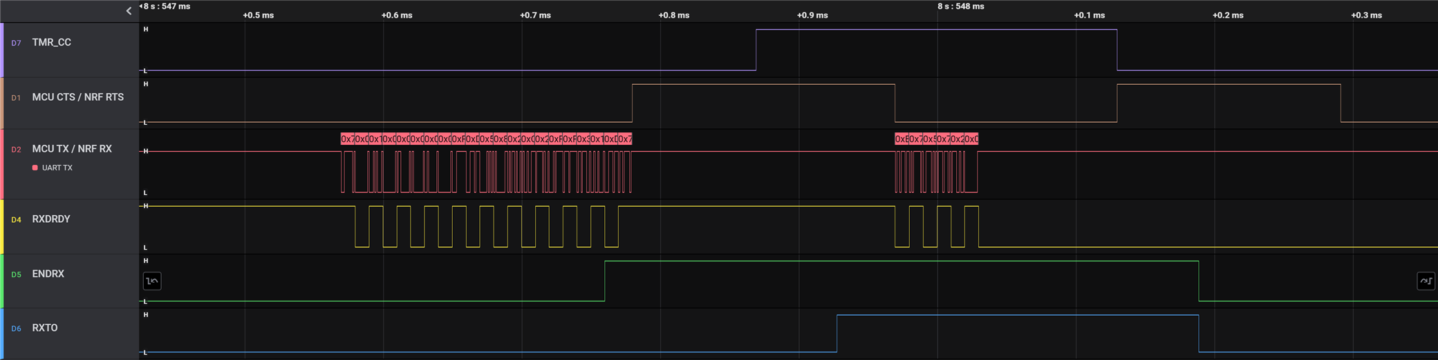
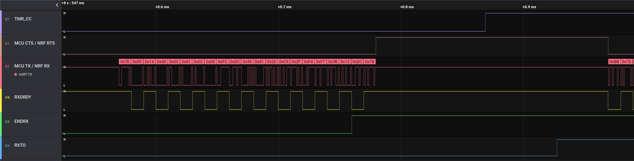
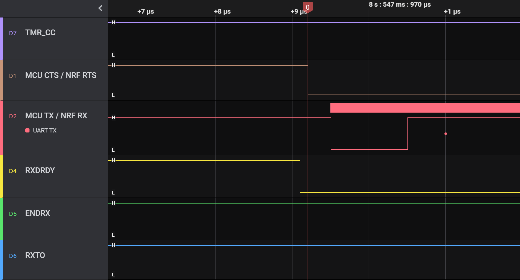
In my understanding, the RXDRDY event is triggered when a byte is fully received in the RX pin (at the stop bit). Then, after the RX FIFO and DMA it will eventually be written to RAM.

My code, similarly to libuarte_async, uses a TIMER to detect when there is no more activity in RX and another TIMER to count the number of RXDRDY events, which should represent the number of bytes physically received at the RX pin.

The problem is, the number of RXDRDY events is sometimes not what I would expect. For instance, consider this trace:

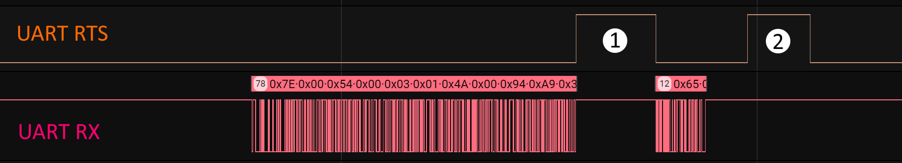
At [1], the RXTO irq handler runs because the DMA transfer is complete. As you can see, 78 bytes were received up to that point. The RXD.AMOUNT register reads 76 and the RXDRDY count is 77. I would expect the RXDRDY count to be 78.

Then, at [2], the RXTO irq handler runs because the reception is stopped due to RX idle. At this point, the RXD.AMOUNT register reads 14 and the RXDRDY count is 13. I would expect the RXDRDY count to be 12.

In short, it looks like the RXDRDY event is not triggered when a byte is received at the RX pin.

Can you please shed some light on this behaviour?

  • Hi,

    Can you post your code showing how you configure the timer to count the events, and how you do the timeout?

    Hard to see from your image, but is any of the bytes sent right after the RTS line is deactivated? The UART(E) peripheral has a HW RX FIFO that can hold up to 4 bytes, as described in the peripheral documentation. Do you trigger the STOPRX and/or FLUSHRX task at any point?

    Best regards,
    Jørgen

  • Here's the relevant code:

        //Configure RX count timer
        nrfx_timer_config_t tmr_config_count = NRFX_TIMER_DEFAULT_CONFIG;
        tmr_config_count.mode = NRF_TIMER_MODE_COUNTER;
        tmr_config_count.p_context = (void *)p_serial;
        ret = nrfx_timer_init(p_serial->p_timer_rxcount, &tmr_config_count, timer_rxcount_evt_handler);
        if (ret != NRFX_SUCCESS)
            return NRF_ERROR_INTERNAL;
        nrfx_timer_enable(p_serial->p_timer_rxcount);
    
        //Configure RX timeout timer
        nrfx_timer_config_t tmr_config_timeout = NRFX_TIMER_DEFAULT_CONFIG;
        tmr_config_timeout.frequency = NRF_TIMER_FREQ_1MHz;
        tmr_config_timeout.p_context = (void *)p_serial;
        ret = nrfx_timer_init(p_serial->p_timer_rxtimeout, &tmr_config_timeout, timer_rxtimeout_evt_handler);
        if (ret != NRFX_SUCCESS)
            return NRF_ERROR_INTERNAL;
        nrfx_timer_compare(p_serial->p_timer_rxtimeout, NRF_TIMER_CC_CHANNEL0, p_config->timeout_us, false);
    
        // ...
        
        //  When a byte is received, increment RX count timer
        PPI_CH_SETUP(p_serial->p_ctrl_blk->ppi_channels[SERIALPORT_PPI_CH_0],
                     nrf_uarte_event_address_get(p_serial->uarte, NRF_UARTE_EVENT_RXDRDY),
                     nrfx_timer_task_address_get(p_serial->p_timer_rxcount, NRF_TIMER_TASK_COUNT),
                     NULL);
        //  When a byte is received, restart RX timeout timer
        PPI_CH_SETUP(p_serial->p_ctrl_blk->ppi_channels[SERIALPORT_PPI_CH_1],
                     nrf_uarte_event_address_get(p_serial->uarte, NRF_UARTE_EVENT_RXDRDY),
                     nrfx_timer_task_address_get(p_serial->p_timer_rxtimeout, NRF_TIMER_TASK_START),
                     nrfx_timer_task_address_get(p_serial->p_timer_rxtimeout, NRF_TIMER_TASK_CLEAR));
        //  On RX timeout timer compare, stop it and stop UART RX
        PPI_CH_SETUP(p_serial->p_ctrl_blk->ppi_channels[SERIALPORT_PPI_CH_2],
                     nrfx_timer_compare_event_address_get(p_serial->p_timer_rxtimeout, 0),
                     nrfx_timer_task_address_get(p_serial->p_timer_rxtimeout, NRF_TIMER_TASK_STOP),
                     nrf_uarte_task_address_get(p_serial->uarte, NRF_UARTE_TASK_STOPRX));
    

    When the RX timeout timer compares, it triggers the STOPRX task on the UARTE.

    My RXTO irq handler then reads the RXD.AMOUNT register and the value of the other timer which I use to count the RXDRDY events.

    On that image, no more bytes are sent when the RTS is deasserted.

    No, I don't trigger FLUSHRX. If there's extra data in the RX FIFO, I'm fine with it being read when I setup the next DMA transaction, but I need to know if there's data there so I can manually restart the RX timeout timer. I need to do that because I manually stop the RX timeout timer at the beginning of the RXTO handler. Which, in turn, I do because the RX timeout timer is stopped by PPI on the RX timeout timer Compare event, but up to 4 extra bytes could be received, and those RXDRDY events would make PPI restart the RX timer.

    It's a bit mind-bending, I hope that makes sense.

    But I just want to know when the RXDRDY event is triggered. It appears it's not when the stop bit is received at the RX pin, like the docs suggest.

  • Would you be able to output the events (RXDRDY, RXTO, END, COMPARE event) on GPIOs, to read out with the logic analyzer how the events are generated compared to your incoming data and task triggering? You can PPI and GPIOTE to setup this.

    Also, if you can provide a minimal example that can be used to reproduce the behavior you are seeing, that would help us give you a better answer.

  • Here's a capture with the events, as requested. GPIOTE is set to toggle the pins when the event occours.

    Zoomed:

    In this example:

    21 bytes are received in the first block, but AMOUNT is 19 and RXDRDY count is 20. You can see that there was no RXDRDY event for the last byte. Instead, the RXDRDY for that byte occurs immediately before reasserting RTS. Here's a zoomed view:

Related