Program to interface Grove Four Digit Display(TM1637) with nRF chips

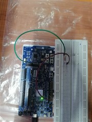
I am trying to interface the Grove 4 Digit Display(TM1637) with the nRF52840 DK.I have successfully interfaced it with ESP32 and get clear output after researching for the CODE in the Internet.I have included that code , below:

main.c

#include "tm1637.h"

#include <stdlib.h>
#include <stdbool.h>
#include <string.h>
#include <math.h>
#include <drivers/gpio.h>

#define CONFIG_TM1637_CLK_PIN 20
#define CONFIG_TM1637_DIO_PIN 21

const gpio_num_t LED_CLK = CONFIG_TM1637_CLK_PIN;
const gpio_num_t LED_DTA = CONFIG_TM1637_DIO_PIN;

void app_main(void)
{
    tm1637_led_t * lcd = tm1637_init(LED_CLK, LED_DTA);
    tm1637_set_number(lcd, 8008); //Displays Number 8008 on Four Digit Display
    tm1637_set_brightness(lcd, 7);
}

tm1637.h

#ifndef TM1637_H
#define TM1637_H

#include <inttypes.h>
#include <stdbool.h>
#include <drivers/gpio.h>

#ifdef __cplusplus
extern "C" {
#endif

struct tm;

typedef enum {
    GPIO_NUM_20 = 20,     /*!< GPIO0, input and output ,Can take any of these two pins as CLK and DIO*/
    GPIO_NUM_21 = 21, 
    GPIO_NUM_22 = 22,
    GPIO_NUM_23 = 23,     //This is the GPIO definition in ESP32, But I don't know how to define GPIO 
    GPIO_NUM_24 = 24,     // pins for nRF52840 chips.Please help me to find the solution to this part
    GPIO_NUM_25 = 25,    
    GPIO_NUM_26 = 26
} gpio_num_t;

typedef struct {
	gpio_num_t m_pin_clk;
	gpio_num_t m_pin_dta;
	uint8_t m_brightness;
} tm1637_led_t;

/**
 * @brief Constructs new LED TM1637 object
 *
 * @param pin_clk GPIO pin for CLK input of LED module
 * @param pin_data GPIO pin for DIO input of LED module
 * @return
 */
tm1637_led_t * tm1637_init(gpio_num_t pin_clk, gpio_num_t pin_data);

/**
 * @brief Set brightness level. Note - will be set after next display render
 * @param led LED object
 * @param level Brightness level 0..7 value
 */
void tm1637_set_brightness(tm1637_led_t * led, uint8_t level);

/**
 * @brief Set one-segment number, also controls dot of this segment
 * @param led LED object
 * @param segment_idx Segment index (0..3)
 * @param num Number to set (0x00..0x0F, 0xFF for clear)
 * @param dot Display dot of this segment
 */
void tm1637_set_segment_number(tm1637_led_t * led, const uint8_t segment_idx, const uint8_t num, const bool dot);

/**
 * @brief Set one-segment raw segment data
 * @param led LED object
 * @param segment_idx Segment index (0..3)
 * @param data Raw data, bitmask is XGFEDCBA
 */
void tm1637_set_segment_raw(tm1637_led_t * led, const uint8_t segment_idx, const uint8_t data);

/**
 * @brief Set full display number, in decimal encoding
 * @param led LED object
 * @param number Display number (0...9999)
 */
void tm1637_set_number(tm1637_led_t * led, uint16_t number);

/**
 * @brief Set full display number, in decimal encoding + control leading zero
 * @param led LED object
 * @param number Display number (0...9999)
 * @param lead_zero Display leading zero(s)
 */
void tm1637_set_number_lead(tm1637_led_t * led, uint16_t number, const bool lead_zero);

/**
 * @brief Set full display number, in decimal encoding + control leading zero + control dot display
 * @param led LED object
 * @param number Display number (0...9999)
 * @param lead_zero Display leading zero(s)
 * @param dot_mask Dot mask, bits left-to-right
 */
void tm1637_set_number_lead_dot(tm1637_led_t * led, uint16_t number, const bool lead_zero, const uint8_t dot_mask);

/**
 * @brief Set full display OFF
 * @param led LED object
 */
void tm1637_display_off(tm1637_led_t *led, uint16_t number, bool lead_zero, const uint8_t dot_mask);

#ifdef __cplusplus
}
#endif

#endif // TM1637_H

tm1637.c

#include "tm1637.h"

#include <stdlib.h>
#include <stdbool.h>
#include <string.h>
#include <math.h>
#include <drivers/gpio.h>

#define TM1637_ADDR_AUTO 0x40
#define TM1637_ADDR_FIXED 0x44

#define MINUS_SIGN_IDX 16

static const int8_t tm1637_symbols[] = {
    // XGFEDCBA
    0x3f, // 0b00111111,    // 0
    0x06, // 0b00000110,    // 1
    0x5b, // 0b01011011,    // 2
    0x4f, // 0b01001111,    // 3
    0x66, // 0b01100110,    // 4
    0x6d, // 0b01101101,    // 5
    0x7d, // 0b01111101,    // 6
    0x07, // 0b00000111,    // 7
    0x7f, // 0b01111111,    // 8
    0x6f, // 0b01101111,    // 9
    0x77, // 0b01110111,    // A
    0x7c, // 0b01111100,    // b
    0x39, // 0b00111001,    // C
    0x5e, // 0b01011110,    // d
    0x79, // 0b01111001,    // E
    0x71, // 0b01110001     // F
    0x40, // 0b01000000     // minus sign
};

void tm1637_start(tm1637_led_t *led);
void tm1637_stop(tm1637_led_t *led);
void tm1637_off(tm1637_led_t *led);
static void tm1637_send_byte(tm1637_led_t *led, uint8_t byte);
static void tm1637_delay();

static inline float nearestf(float val, int precision)
{
    int scale = pow(10, precision);
    return roundf(val * scale) / scale;
}

void tm1637_start(tm1637_led_t *led)
{
    // Send start signal
    // Both outputs are expected to be HIGH beforehand
    gpio_pin_set(dev, led->m_pin_dta, 0);
    tm1637_delay();
}

void tm1637_stop(tm1637_led_t *led)
{
    // Send stop signal
    // CLK is expected to be LOW beforehand
    gpio_pin_set(dev, led->m_pin_dta, 0);
    tm1637_delay();
    gpio_pin_set(dev, led->m_pin_clk, 1);
    tm1637_delay();
    gpio_pin_set(dev, led->m_pin_dta, 1);
    tm1637_delay();
}


void tm1637_send_byte(tm1637_led_t *led, uint8_t byte)
{
    for (uint8_t i = 0; i < 8; ++i)
    {
        gpio_pin_set(dev, led->m_pin_clk, 0);
        tm1637_delay();
        gpio_pin_set(dev, led->m_pin_dta, byte & 0x01); // Send current bit
        byte >>= 1;
        tm1637_delay();
        gpio_pin_set(dev, led->m_pin_clk, 1);
        tm1637_delay();
    }

    // The TM1637 signals an ACK by pulling DIO low from the falling edge of
    // CLK after sending the 8th bit, to the next falling edge of CLK.
    // DIO needs to be set as input during this time to avoid having both
    // chips trying to drive DIO at the same time.
    gpio_pin_configure(dev, led->m_pin_dta, GPIO_INPUT);
    gpio_pin_set(dev, led->m_pin_clk, 0); // TM1637 starts ACK (pulls DIO low)
    tm1637_delay();
    gpio_pin_set(dev, led->m_pin_clk, 1);
    tm1637_delay();
    gpio_pin_set(dev, led->m_pin_clk, 0); // TM1637 ends ACK (releasing DIO)
    tm1637_delay();
    gpio_pin_configure(dev, led->m_pin_dta, GPIO_OUTPUT);
}

void tm1637_delay()
{
    hal_delay(3);
}

// PUBLIC PART:

tm1637_led_t *tm1637_init(gpio_num_t pin_clk, gpio_num_t pin_data)
{
    const struct device *dev;

    tm1637_led_t *led = (tm1637_led_t *)malloc(sizeof(tm1637_led_t));
    led->m_pin_clk = pin_clk;
    led->m_pin_dta = pin_data;
    led->m_brightness = 0x06;
    // Set CLK to low during DIO initialization to avoid sending a start signal by mistake
    gpio_pin_configure(dev, pin_clk, GPIO_OUTPUT);
    gpio_pin_set(dev, pin_clk, 0);
    tm1637_delay();
    gpio_pin_configure(dev, pin_data, GPIO_OUTPUT);
    gpio_pin_set(dev, pin_data, 1);
    tm1637_delay();
    gpio_pin_set(dev, pin_clk, 1);
    tm1637_delay();
    return led;
}

void tm1637_set_brightness(tm1637_led_t *led, uint8_t level)
{
    if (level > 0x07)
    {
        level = 0x07;
    } // Check max level
    led->m_brightness = level;
}

void tm1637_set_segment_number(tm1637_led_t *led, const uint8_t segment_idx, const uint8_t num, const bool dot)
{
    uint8_t seg_data = 0x00;

    if (num < (sizeof(tm1637_symbols) / sizeof(tm1637_symbols[0])))
    {
        seg_data = tm1637_symbols[num]; // Select proper segment image
    }

    if (dot)
    {
        seg_data |= 0x80; // Set DOT segment flag
    }

    tm1637_set_segment_raw(led, segment_idx, seg_data);
}

void tm1637_set_segment_raw(tm1637_led_t *led, const uint8_t segment_idx, const uint8_t data)
{
    tm1637_start(led);
    tm1637_send_byte(led, TM1637_ADDR_FIXED);
    tm1637_stop(led);
    tm1637_start(led);
    tm1637_send_byte(led, segment_idx | 0xc0);
    tm1637_send_byte(led, data);
    tm1637_stop(led);
    tm1637_start(led);
    tm1637_send_byte(led, led->m_brightness | 0x88);
    tm1637_stop(led);
}

void tm1637_set_number(tm1637_led_t *led, uint16_t number)
{
    tm1637_set_number_lead_dot(led, number, false, 0x00);
}

void tm1637_set_number_lead(tm1637_led_t *led, uint16_t number, const bool lead_zero)
{
    tm1637_set_number_lead_dot(led, number, lead_zero, 0x00);
}

void tm1637_set_number_lead_dot(tm1637_led_t *led, uint16_t number, bool lead_zero, const uint8_t dot_mask)
{
    uint8_t lead_number = lead_zero ? 0xFF : tm1637_symbols[0];

    if (number < 10)
    {
        tm1637_set_segment_number(led, 3, number, dot_mask & 0x01);
        tm1637_set_segment_number(led, 2, lead_number, dot_mask & 0x02);
        tm1637_set_segment_number(led, 1, lead_number, dot_mask & 0x04);
        tm1637_set_segment_number(led, 0, lead_number, dot_mask & 0x08);
    }
    else if (number < 100)
    {
        tm1637_set_segment_number(led, 3, number % 10, dot_mask & 0x01);
        tm1637_set_segment_number(led, 2, (number / 10) % 10, dot_mask & 0x02);
        tm1637_set_segment_number(led, 1, lead_number, dot_mask & 0x04);
        tm1637_set_segment_number(led, 0, lead_number, dot_mask & 0x08);
    }
    else if (number < 1000)
    {
        tm1637_set_segment_number(led, 3, number % 10, dot_mask & 0x01);
        tm1637_set_segment_number(led, 2, (number / 10) % 10, dot_mask & 0x02);
        tm1637_set_segment_number(led, 1, (number / 100) % 10, dot_mask & 0x04);
        tm1637_set_segment_number(led, 0, lead_number, dot_mask & 0x08);
    }
    else
    {
        tm1637_set_segment_number(led, 3, number % 10, dot_mask & 0x01);
        tm1637_set_segment_number(led, 2, (number / 10) % 10, dot_mask & 0x02);
        tm1637_set_segment_number(led, 1, (number / 100) % 10, dot_mask & 0x04);
        tm1637_set_segment_number(led, 0, (number / 1000) % 10, dot_mask & 0x08);
    }
}


void tm1637_display_off(tm1637_led_t *led, uint16_t number, bool lead_zero, const uint8_t dot_mask)
{
    uint8_t lead_number = lead_zero ? 0xFF : tm1637_symbols[0];

    
        tm1637_set_segment_number(led, 3, lead_number, dot_mask & 0x01);
        tm1637_set_segment_number(led, 2, lead_number, dot_mask & 0x02);
        tm1637_set_segment_number(led, 1, lead_number, dot_mask & 0x04);
        tm1637_set_segment_number(led, 0, lead_number, dot_mask & 0x08);
}

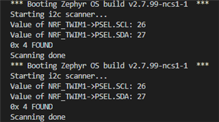
I have modified the above code to work for nRF52840 DK as well as nRF52840 Dongle.So only I won't use the SCL and SDA pins .

Problems:

1)In ESP32 , they have gpio_types.h file, where they declared the GPIO pin numbers in enum as gpio_num_t. But , for nordic chips , I don't find any such file for GPIO definition and declaration.Where can I find such declaration for GPIO pins in Nordic chips?

2)In tm1637.c file, line number : 98 , I have use hal_delay() function to delay.Is it the correct One?

3)I have finished all the program in DevAcademy for Nordic chips.In that they use Device tree to define LEDs and BUTTONs in the DK.But it won't give any steps to define the separete GPIO pins.If I have to declare the GPIO pins in Device tree , Please explain me How to do that...

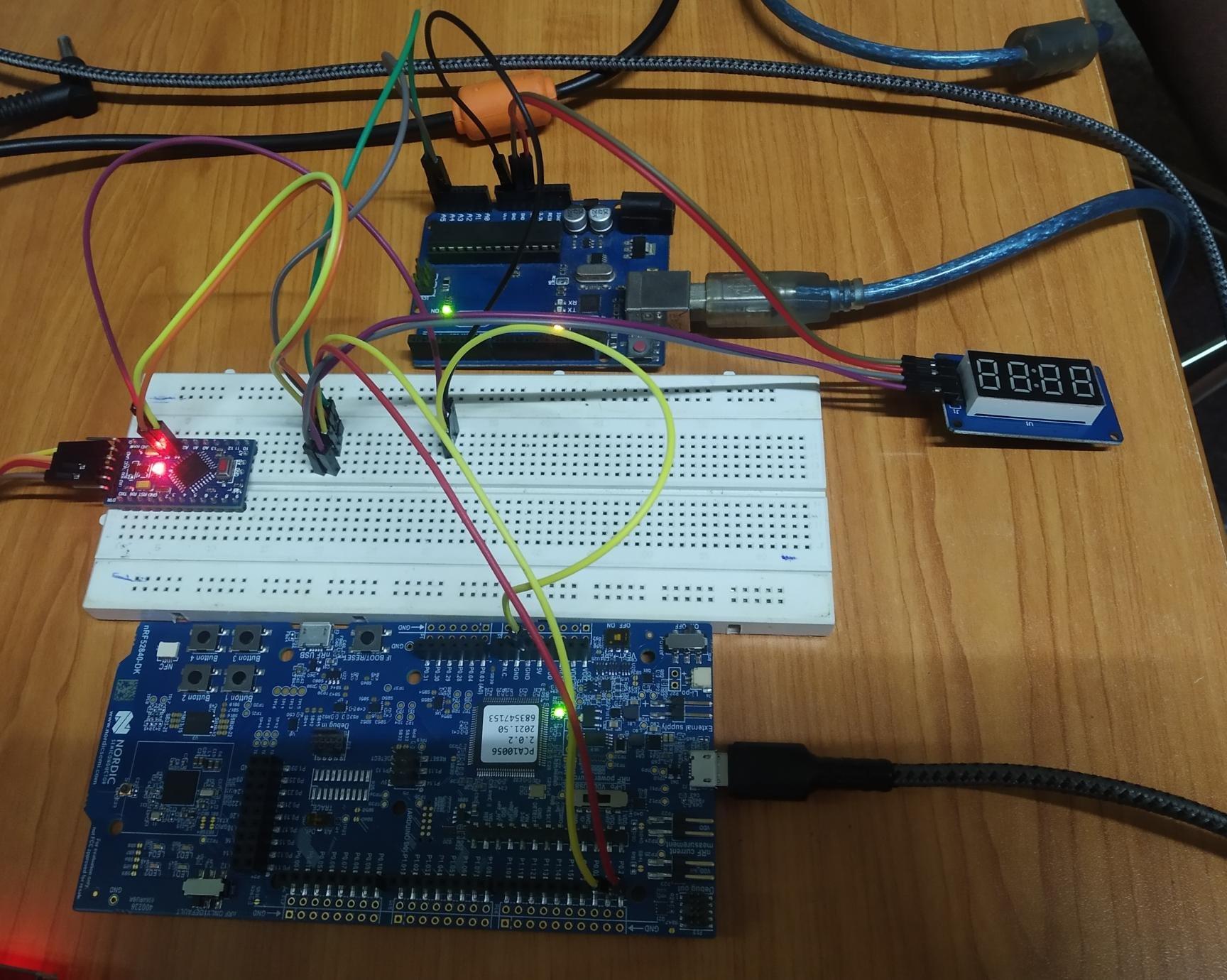
One more thing.This program perfectly works for ESP32 and I got the desired OUTPUT on the Four Digit Seven Segment Display.This clearly shows the logic of the program is correct.I have to know , How can I implement same logic in nRF chips?

Please reply as soon as possible.

Thankyou.

-Vicky.

Parents
  • After searching different Questions and Answers in Devzone, I came to the point , that I have to change the Device Tree by including Overlay file in the root folder of the main function. I have made a simple program to blink an LED connected to the GPIO pin 22 which is declared as CLK.

    Refernce

    Device Tree Overlay Program Reference

    I have included the main.c function and the overlay file below:

    main.c

    #include <zephyr.h>
    #include <device.h>
    #include <devicetree.h>
    #include <drivers/gpio.h>
    
    /* Increase the main thread sleep time from 100ms to 1 second  */
    #define SLEEP_TIME_MS 1000
    
    
    //Defining GPIO pins
    #define CLK_NODE DT_ALIAS(gpiocus0)
    #if DT_NODE_HAS_STATUS(CLK_NODE, okay)
    #define CLK DT_GPIO_LABEL(CLK_NODE, gpios)
    #define CLK_PIN DT_GPIO_PIN(CLK_NODE, gpios)
    #define CLK_FLAGS DT_GPIO_FLAGS(CLK_NODE, gpios)
    #else
    #error "Unsupported board: gpio22 devicetree alias is not defined"
    #endif
    
    #define DIO_NODE DT_ALIAS(gpiocus1)
    #if DT_NODE_HAS_STATUS(DIO_NODE, okay)
    #define DIO DT_GPIO_LABEL(DIO_NODE, gpios)
    #define DIO_PIN DT_GPIO_PIN(DIO_NODE, gpios)
    #define DIO_FLAGS DT_GPIO_FLAGS(DIO_NODE, gpios)
    #else
    #error "Unsupported board: gpio24 devicetree alias is not defined"
    #endif
    
    
    void main(void)
    {
        const struct device *dev;
        bool led_is_on = true;
        int ret;
        
        dev = device_get_binding(CLK);
        if (dev == NULL) 
        {
            return;
        }
        
        ret = gpio_pin_configure(dev, CLK_PIN, GPIO_OUTPUT_ACTIVE | CLK_FLAGS);
        if (ret < 0) 
        {
            return;
        }
    
        while (1) 
        {
            gpio_pin_set(dev, CLK_PIN, (int)led_is_on);
            led_is_on = !led_is_on;
            k_msleep(SLEEP_TIME_MS);
        }
    }

    Device tree overlay file:

    / {
        gpiocustom {
            compatible = "gpio-keys";
            gpiocus0: gpiocus_0 {
                gpios = <&gpio0 22 GPIO_ACTIVE_LOW>;
                label = "Custom gpio 22";
            };
            gpiocus1: gpiocus_1 {
                gpios = <&gpio0 23 GPIO_ACTIVE_LOW>;
                label = "Custom gpio 24";
            };
        };
        aliases {
            gpiocus0 = &gpiocus0;
            gpiocus1 = &gpiocus1;
        };
    };

    The screenshot of my VS Code workspace:

    Hardware setup and wiring diagram :

    This is my hardware setup to blink an LED connected to GPIO pin no : 22.

    If you notice any error in my wiring circuit , Please notify that.

    I have Pristine build the above code without any errors.But , when I flash it in thw nRF52840 DK board, I won't get any output. I connected an LED at GPIO pin 22 with required resistor. I don't know what am I missing?Can you tell me how can I solve this problem?

    Ultimately I have to control the 4 Digit Display using these two GPIO pins. If you have idea to do that, Please tell me how can I achieve that.

    Thankyou.

    -Vicky

  • Hello Vicky,

    Sorry for the late reply. I've had a couple of non-planned days out of office since I was assigned your case. 

    So you are not seeing any changes in the GPIO at all?

    I see that you are using the pins 20 and 21. I assume you didn't do any changes/modifications to the DK? If so, then the pins P0.17 -> P0.23 are not connected to the GPIO headers that you are trying to use. If you look at the back of your DK, you can see that these are connected to a QSPI bus attached to an external flash chip on the DK. So the easiest workaround for this is to use some other pins. Try e.g. P0.26 and P0.27.

    It is correct that you need to set up an overlay file like you did, so try changing the pins to see if they will light up the LED. 

    Even if they do light it up, though, bitbanging (emulating SPI) is not straight forward when you are using NCS, which is a real time operating system (RTOS). Is there a reason why you need to bitbang it like this, and not use SPI? Actually using the SPI peripheral will give you much better timing control. Assuming the driver that you have found is working, you should be able to just send the bytes that you are bitbanging here over SPI instead of stepping through bit by bit. 

    Since you are so close, though, try replacing the pins. What does your tm1637_delay() look like? Tru using "k_sleep(K_MSEC(100));" . That is 100ms, so you may want to turn it down. But unfortunately, the k_sleep works less good with shorter delays, because it hands the control over to other part of the RTOS, and it will get it back when it is done with it's other work.

    If you want to check out an example using SPI, I can recommend that you check out this github's SPI sample:

    https://github.com/sigurdnev/ncs-playground/tree/master/samples

    If you for some reason need to bitbang this, I suggest you check out the nRF5 SDK, which is a more bare metal SDK, without the RTOS. There you will have more control of the timing in the application. But only as long as you are not using the Bluetooth Low Energy stack, because then it will have the highest priority, and you are pretty much in the same situation.

    Best regards,

    Edvin

  • Hi Edwin,
    Thankyou for your suggestion. I used Pin 26 and 27 for my Push Button , LED project and it worked perfectly.

    I want to interface that TM1637 Display with the nRF52840 Dongle.So that, I used the normal bit banging method to control my display.
    I have modified the above code to work for the DK .It get build successfully without any errors.But it won't produce any output for the
    Display.I will show the modified code below.Can you tell me , what am I missing in that?

    main.c

    #include <zephyr.h>
    #include <sys/printk.h>
    #include "myfunction.h"
    
    #include <stdlib.h>
    #include <stdbool.h>
    #include <string.h>
    #include <math.h>
    #include <device.h>
    #include <devicetree.h>
    #include <drivers/gpio.h>
    
    #define CONFIG_TM1637_CLK_PIN 26
    #define CONFIG_TM1637_DTA_PIN 27
    
    const gpio_num_t CLK = CONFIG_TM1637_CLK_PIN;
    const gpio_num_t DTA = CONFIG_TM1637_DTA_PIN;
    
    const gpio_num_pin_t CLK_PIN = CONFIG_TM1637_CLK_PIN;
    const gpio_num_pin_t DTA_PIN = CONFIG_TM1637_DTA_PIN;
    
    void main(void)
    {
    	int a = 8, b = 92;
    	printk("The sum of %d and %d is %d\n\r", a, b, sum(a,b));
    	tm1637_led_t * lcd = tm1637_init(CLK, DTA, CLK_PIN, DTA_PIN);
    	tm1637_set_number(lcd, 8008); //Displays Number 8008 on Four Digit Display
    	tm1637_set_brightness(lcd, 7);
    	
    }

    myfunction.c

    #include "myfunction.h"
    
    int sum(int a, int b){
        return a+b;
    }
    
    /*#include <stdlib.h>
    #include <stdbool.h>
    #include <string.h>
    #include <math.h>
    #include <zephyr.h>
    #include <device.h>
    #include <devicetree.h>
    #include <drivers/gpio.h>
    #include <sys/printk.h>*/
    
    #define TM1637_ADDR_AUTO 0x40
    #define TM1637_ADDR_FIXED 0x44
    
    #define MINUS_SIGN_IDX 16
    
    static const int8_t tm1637_symbols[] = {
        // XGFEDCBA
        0x3f, // 0b00111111,    // 0
        0x06, // 0b00000110,    // 1
        0x5b, // 0b01011011,    // 2
        0x4f, // 0b01001111,    // 3
        0x66, // 0b01100110,    // 4
        0x6d, // 0b01101101,    // 5
        0x7d, // 0b01111101,    // 6
        0x07, // 0b00000111,    // 7
        0x7f, // 0b01111111,    // 8
        0x6f, // 0b01101111,    // 9
        0x77, // 0b01110111,    // A
        0x7c, // 0b01111100,    // b
        0x39, // 0b00111001,    // C
        0x5e, // 0b01011110,    // d
        0x79, // 0b01111001,    // E
        0x71, // 0b01110001     // F
        0x40, // 0b01000000     // minus sign
    };
    
    void tm1637_start(tm1637_led_t *led);
    void tm1637_stop(tm1637_led_t *led);
    void tm1637_off(tm1637_led_t *led);
    void tm1637_send_byte(tm1637_led_t *led, uint8_t byte);
    void tm1637_delay();
    // PUBLIC PART:
    //Defining GPIO pins
    #define CLK_NODE DT_ALIAS(gpiocus0)
    
    #if DT_NODE_HAS_STATUS(CLK_NODE, okay)
    #define CLOCK DT_GPIO_LABEL(CLK_NODE, gpios)
    #define CLOCK_PIN DT_GPIO_PIN(CLK_NODE, gpios)
    #define CLOCK_FLAGS DT_GPIO_FLAGS(CLK_NODE, gpios)
    #else
    #error "Unsupported board: gpio22 devicetree alias is not defined"
    #endif
    
    #define DTA_NODE DT_ALIAS(gpiocus1)
    
    #if DT_NODE_HAS_STATUS(DTA_NODE, okay)
    #define DATA DT_GPIO_LABEL(DTA_NODE, gpios)
    #define DATA_PIN DT_GPIO_PIN(DTA_NODE, gpios)
    #define DATA_FLAGS DT_GPIO_FLAGS(DTA_NODE, gpios)
    #else
    #error "Unsupported board: gpio24 devicetree alias is not defined"
    #endif
    const struct device *dev;
    
    tm1637_led_t *tm1637_init(gpio_num_t clk, gpio_num_t data, gpio_num_pin_t pin_clk, gpio_num_pin_t pin_data)
    {
        
        printk("Struct Working One");
        dev = device_get_binding(CLOCK);
    
        tm1637_led_t *led = (tm1637_led_t *)malloc(sizeof(tm1637_led_t));
        led->m_clk = clk;
        led->m_dta = data;
        led->m_clk_pin = pin_clk;
        led->m_dta_pin = pin_data;
        led->m_brightness = 0x06;
        // Set CLK to low during DIO initialization to avoid sending a start signal by mistake
        gpio_pin_configure(dev, pin_clk, GPIO_OUTPUT_ACTIVE | CLOCK_FLAGS);
        gpio_pin_set(dev, clk, 0);
        tm1637_delay();
        gpio_pin_configure(dev, data, GPIO_OUTPUT_ACTIVE | CLOCK_FLAGS);
        gpio_pin_set(dev, pin_data, 1);
        tm1637_delay();
        gpio_pin_set(dev, pin_clk, 1);
        tm1637_delay();
        return led;
    }
    
    
    void tm1637_delay()
    {
        k_sleep(K_MSEC(3));
        //hal_delay(3);
    }
    
    void tm1637_start(tm1637_led_t *led)
    {
        // Send start signal
        // Both outputs are expected to be HIGH beforehand
        gpio_pin_set(dev, led->m_dta_pin, 0);
        tm1637_delay();
    }
    
    void tm1637_stop(tm1637_led_t *led)
    {
        // Send stop signal
        // CLK is expected to be LOW beforehand
        gpio_pin_set(dev, led->m_dta_pin, 0);
        tm1637_delay();
        gpio_pin_set(dev, led->m_clk_pin, 1);
        tm1637_delay();
        gpio_pin_set(dev, led->m_dta_pin, 1);
        tm1637_delay();
    }


    void tm1637_send_byte(tm1637_led_t *led, uint8_t byte)
    {
        for (uint8_t i = 0; i < 8; ++i)
        {
            gpio_pin_set(dev, led->m_clk_pin, 0);
            tm1637_delay();
            gpio_pin_set(dev, led->m_dta_pin, byte & 0x01); // Send current bit
            byte >>= 1;
            tm1637_delay();
            gpio_pin_set(dev, led->m_clk_pin, 1);
            tm1637_delay();
        }
    
        // The TM1637 signals an ACK by pulling DIO low from the falling edge of
        // CLK after sending the 8th bit, to the next falling edge of CLK.
        // DIO needs to be set as input during this time to avoid having both
        // chips trying to drive DIO at the same time.
        gpio_pin_configure(dev, led->m_dta, GPIO_INPUT);
        gpio_pin_set(dev, led->m_clk_pin, 0); // TM1637 starts ACK (pulls DIO low)
        tm1637_delay();
        gpio_pin_set(dev, led->m_clk_pin, 1);
        tm1637_delay();
        gpio_pin_set(dev, led->m_clk_pin, 0); // TM1637 ends ACK (releasing DIO)
        tm1637_delay();
        gpio_pin_configure(dev, led->m_dta, GPIO_OUTPUT_ACTIVE);
    }


    void tm1637_set_brightness(tm1637_led_t *led, uint8_t level)
    {
        if (level > 0x07)
        {
            level = 0x07;
        } // Check max level
        led->m_brightness = level;
    }
    
    void tm1637_set_segment_number(tm1637_led_t *led, const uint8_t segment_idx, const uint8_t num, const bool dot)
    {
        uint8_t seg_data = 0x00;
    
        if (num < (sizeof(tm1637_symbols) / sizeof(tm1637_symbols[0])))
        {
            seg_data = tm1637_symbols[num]; // Select proper segment image
        }
    
        if (dot)
        {
            seg_data |= 0x80; // Set DOT segment flag
        }
    
        tm1637_set_segment_raw(led, segment_idx, seg_data);
    }
    
    void tm1637_set_segment_raw(tm1637_led_t *led, const uint8_t segment_idx, const uint8_t data)
    {
        tm1637_start(led);
        tm1637_send_byte(led, TM1637_ADDR_FIXED);
        tm1637_stop(led);
        tm1637_start(led);
        tm1637_send_byte(led, segment_idx | 0xc0);
        tm1637_send_byte(led, data);
        tm1637_stop(led);
        tm1637_start(led);
        tm1637_send_byte(led, led->m_brightness | 0x88);
        tm1637_stop(led);
    }
    
    void tm1637_set_number(tm1637_led_t *led, uint16_t number)
    {
        tm1637_set_number_lead_dot(led, number, false, 0x00);
    }
    
    void tm1637_set_number_lead(tm1637_led_t *led, uint16_t number, const bool lead_zero)
    {
        tm1637_set_number_lead_dot(led, number, lead_zero, 0x00);
    }
    
    void tm1637_set_number_lead_dot(tm1637_led_t *led, uint16_t number, bool lead_zero, const uint8_t dot_mask)
    {
        uint8_t lead_number = lead_zero ? 0xFF : tm1637_symbols[0];
    
        if (number < 10)
        {
            tm1637_set_segment_number(led, 3, number, dot_mask & 0x01);
            tm1637_set_segment_number(led, 2, lead_number, dot_mask & 0x02);
            tm1637_set_segment_number(led, 1, lead_number, dot_mask & 0x04);
            tm1637_set_segment_number(led, 0, lead_number, dot_mask & 0x08);
        }
        else if (number < 100)
        {
            tm1637_set_segment_number(led, 3, number % 10, dot_mask & 0x01);
            tm1637_set_segment_number(led, 2, (number / 10) % 10, dot_mask & 0x02);
            tm1637_set_segment_number(led, 1, lead_number, dot_mask & 0x04);
            tm1637_set_segment_number(led, 0, lead_number, dot_mask & 0x08);
        }
        else if (number < 1000)
        {
            tm1637_set_segment_number(led, 3, number % 10, dot_mask & 0x01);
            tm1637_set_segment_number(led, 2, (number / 10) % 10, dot_mask & 0x02);
            tm1637_set_segment_number(led, 1, (number / 100) % 10, dot_mask & 0x04);
            tm1637_set_segment_number(led, 0, lead_number, dot_mask & 0x08);
        }
        else
        {
            tm1637_set_segment_number(led, 3, number % 10, dot_mask & 0x01);
            tm1637_set_segment_number(led, 2, (number / 10) % 10, dot_mask & 0x02);
            tm1637_set_segment_number(led, 1, (number / 100) % 10, dot_mask & 0x04);
            tm1637_set_segment_number(led, 0, (number / 1000) % 10, dot_mask & 0x08);
        }
    }
    
    
    void tm1637_display_off(tm1637_led_t *led, uint16_t number, bool lead_zero, const uint8_t dot_mask)
    {
        uint8_t lead_number = lead_zero ? 0xFF : tm1637_symbols[0];
    
        
            tm1637_set_segment_number(led, 3, lead_number, dot_mask & 0x01);
            tm1637_set_segment_number(led, 2, lead_number, dot_mask & 0x02);
            tm1637_set_segment_number(led, 1, lead_number, dot_mask & 0x04);
            tm1637_set_segment_number(led, 0, lead_number, dot_mask & 0x08);
    }

    myfunction.h

    #ifndef MY_FUNCTION_H
    #define MY_FUNCTION_H
    
    int sum(int a, int b);
    
    #include <inttypes.h>
    #include <stdbool.h>
    #include <zephyr.h>
    #include <device.h>
    #include <devicetree.h>
    #include <drivers/gpio.h>
    #include <sys/printk.h>
    #ifdef __cplusplus
    extern "C"
    {
    #endif
    
        struct tm;
    
        typedef enum
        {
            CLOCK = 26, /*!< GPIO0, input and output ,Can take any of these two pins as CLK and DIO*/
            DATA = 27
        } gpio_num_t;
    
        typedef enum
        {
            CLOCK_PIN = 26,
            DATA_PIN = 27
        } gpio_num_pin_t;
    
        typedef struct
        {
            gpio_num_t m_clk;
            gpio_num_t m_dta;
            gpio_num_pin_t m_clk_pin;
            gpio_num_pin_t m_dta_pin;
            uint8_t m_brightness;
        } tm1637_led_t;
    
        tm1637_led_t *tm1637_init(gpio_num_t clk, gpio_num_t data, gpio_num_pin_t pin_clk, gpio_num_pin_t pin_data);
    
        void tm1637_set_brightness(tm1637_led_t *led, uint8_t level);
    
        void tm1637_set_segment_number(tm1637_led_t *led, const uint8_t segment_idx, const uint8_t num, const bool dot);
    
        void tm1637_set_segment_raw(tm1637_led_t *led, const uint8_t segment_idx, const uint8_t data);
    
        void tm1637_set_number(tm1637_led_t *led, uint16_t number);
    
        void tm1637_set_number_lead(tm1637_led_t *led, uint16_t number, const bool lead_zero);
    
        void tm1637_set_number_lead_dot(tm1637_led_t *led, uint16_t number, const bool lead_zero, const uint8_t dot_mask);
    
        void tm1637_display_off(tm1637_led_t *led, uint16_t number, bool lead_zero, const uint8_t dot_mask);
    
    #ifdef __cplusplus
    }
    #endif 
    
    #endif


    If you have any idea on connecting that display to Dongle through I2C connection, Please notify that and guide me to achive that Edvin.It will be
    really helpful for me.

    But only as long as you are not using the Bluetooth Low Energy stack, because then it will have the highest priority, and you are pretty much in the same situation.

    I have to use Bluetooth Mesh Stack for the Dongles along with this Display interface.Then, How can I overcome this problem in Dongle?

    If you want to check out an example using SPI, I can recommend that you check out this github's SPI sample:

    https://github.com/sigurdnev/ncs-playground/tree/master/samples

    I try to build and flash some of the samples in the above mentioned link.But it gives me so many errors and I don't know how to use them as there is no explanation or read me files.

    My final objective is to interface TM1637 Display to nRF52840 Dongle , which run the BLE Mesh model in them.Kinldy guide me to achieve that.And also have a look at the code , I gave above . I spent almot one day to modify that. If it gives clear output to Display numbers , I feel really happy. Or if I have to follow the I2C techniques to interface that Display , Please give some ideas to do that . Ultimately I have to achive my final objective.

    Thankyou .

    -Vicky.

Reply
  • Hi Edwin,
    Thankyou for your suggestion. I used Pin 26 and 27 for my Push Button , LED project and it worked perfectly.

    I want to interface that TM1637 Display with the nRF52840 Dongle.So that, I used the normal bit banging method to control my display.
    I have modified the above code to work for the DK .It get build successfully without any errors.But it won't produce any output for the
    Display.I will show the modified code below.Can you tell me , what am I missing in that?

    main.c

    #include <zephyr.h>
    #include <sys/printk.h>
    #include "myfunction.h"
    
    #include <stdlib.h>
    #include <stdbool.h>
    #include <string.h>
    #include <math.h>
    #include <device.h>
    #include <devicetree.h>
    #include <drivers/gpio.h>
    
    #define CONFIG_TM1637_CLK_PIN 26
    #define CONFIG_TM1637_DTA_PIN 27
    
    const gpio_num_t CLK = CONFIG_TM1637_CLK_PIN;
    const gpio_num_t DTA = CONFIG_TM1637_DTA_PIN;
    
    const gpio_num_pin_t CLK_PIN = CONFIG_TM1637_CLK_PIN;
    const gpio_num_pin_t DTA_PIN = CONFIG_TM1637_DTA_PIN;
    
    void main(void)
    {
    	int a = 8, b = 92;
    	printk("The sum of %d and %d is %d\n\r", a, b, sum(a,b));
    	tm1637_led_t * lcd = tm1637_init(CLK, DTA, CLK_PIN, DTA_PIN);
    	tm1637_set_number(lcd, 8008); //Displays Number 8008 on Four Digit Display
    	tm1637_set_brightness(lcd, 7);
    	
    }

    myfunction.c

    #include "myfunction.h"
    
    int sum(int a, int b){
        return a+b;
    }
    
    /*#include <stdlib.h>
    #include <stdbool.h>
    #include <string.h>
    #include <math.h>
    #include <zephyr.h>
    #include <device.h>
    #include <devicetree.h>
    #include <drivers/gpio.h>
    #include <sys/printk.h>*/
    
    #define TM1637_ADDR_AUTO 0x40
    #define TM1637_ADDR_FIXED 0x44
    
    #define MINUS_SIGN_IDX 16
    
    static const int8_t tm1637_symbols[] = {
        // XGFEDCBA
        0x3f, // 0b00111111,    // 0
        0x06, // 0b00000110,    // 1
        0x5b, // 0b01011011,    // 2
        0x4f, // 0b01001111,    // 3
        0x66, // 0b01100110,    // 4
        0x6d, // 0b01101101,    // 5
        0x7d, // 0b01111101,    // 6
        0x07, // 0b00000111,    // 7
        0x7f, // 0b01111111,    // 8
        0x6f, // 0b01101111,    // 9
        0x77, // 0b01110111,    // A
        0x7c, // 0b01111100,    // b
        0x39, // 0b00111001,    // C
        0x5e, // 0b01011110,    // d
        0x79, // 0b01111001,    // E
        0x71, // 0b01110001     // F
        0x40, // 0b01000000     // minus sign
    };
    
    void tm1637_start(tm1637_led_t *led);
    void tm1637_stop(tm1637_led_t *led);
    void tm1637_off(tm1637_led_t *led);
    void tm1637_send_byte(tm1637_led_t *led, uint8_t byte);
    void tm1637_delay();
    // PUBLIC PART:
    //Defining GPIO pins
    #define CLK_NODE DT_ALIAS(gpiocus0)
    
    #if DT_NODE_HAS_STATUS(CLK_NODE, okay)
    #define CLOCK DT_GPIO_LABEL(CLK_NODE, gpios)
    #define CLOCK_PIN DT_GPIO_PIN(CLK_NODE, gpios)
    #define CLOCK_FLAGS DT_GPIO_FLAGS(CLK_NODE, gpios)
    #else
    #error "Unsupported board: gpio22 devicetree alias is not defined"
    #endif
    
    #define DTA_NODE DT_ALIAS(gpiocus1)
    
    #if DT_NODE_HAS_STATUS(DTA_NODE, okay)
    #define DATA DT_GPIO_LABEL(DTA_NODE, gpios)
    #define DATA_PIN DT_GPIO_PIN(DTA_NODE, gpios)
    #define DATA_FLAGS DT_GPIO_FLAGS(DTA_NODE, gpios)
    #else
    #error "Unsupported board: gpio24 devicetree alias is not defined"
    #endif
    const struct device *dev;
    
    tm1637_led_t *tm1637_init(gpio_num_t clk, gpio_num_t data, gpio_num_pin_t pin_clk, gpio_num_pin_t pin_data)
    {
        
        printk("Struct Working One");
        dev = device_get_binding(CLOCK);
    
        tm1637_led_t *led = (tm1637_led_t *)malloc(sizeof(tm1637_led_t));
        led->m_clk = clk;
        led->m_dta = data;
        led->m_clk_pin = pin_clk;
        led->m_dta_pin = pin_data;
        led->m_brightness = 0x06;
        // Set CLK to low during DIO initialization to avoid sending a start signal by mistake
        gpio_pin_configure(dev, pin_clk, GPIO_OUTPUT_ACTIVE | CLOCK_FLAGS);
        gpio_pin_set(dev, clk, 0);
        tm1637_delay();
        gpio_pin_configure(dev, data, GPIO_OUTPUT_ACTIVE | CLOCK_FLAGS);
        gpio_pin_set(dev, pin_data, 1);
        tm1637_delay();
        gpio_pin_set(dev, pin_clk, 1);
        tm1637_delay();
        return led;
    }
    
    
    void tm1637_delay()
    {
        k_sleep(K_MSEC(3));
        //hal_delay(3);
    }
    
    void tm1637_start(tm1637_led_t *led)
    {
        // Send start signal
        // Both outputs are expected to be HIGH beforehand
        gpio_pin_set(dev, led->m_dta_pin, 0);
        tm1637_delay();
    }
    
    void tm1637_stop(tm1637_led_t *led)
    {
        // Send stop signal
        // CLK is expected to be LOW beforehand
        gpio_pin_set(dev, led->m_dta_pin, 0);
        tm1637_delay();
        gpio_pin_set(dev, led->m_clk_pin, 1);
        tm1637_delay();
        gpio_pin_set(dev, led->m_dta_pin, 1);
        tm1637_delay();
    }


    void tm1637_send_byte(tm1637_led_t *led, uint8_t byte)
    {
        for (uint8_t i = 0; i < 8; ++i)
        {
            gpio_pin_set(dev, led->m_clk_pin, 0);
            tm1637_delay();
            gpio_pin_set(dev, led->m_dta_pin, byte & 0x01); // Send current bit
            byte >>= 1;
            tm1637_delay();
            gpio_pin_set(dev, led->m_clk_pin, 1);
            tm1637_delay();
        }
    
        // The TM1637 signals an ACK by pulling DIO low from the falling edge of
        // CLK after sending the 8th bit, to the next falling edge of CLK.
        // DIO needs to be set as input during this time to avoid having both
        // chips trying to drive DIO at the same time.
        gpio_pin_configure(dev, led->m_dta, GPIO_INPUT);
        gpio_pin_set(dev, led->m_clk_pin, 0); // TM1637 starts ACK (pulls DIO low)
        tm1637_delay();
        gpio_pin_set(dev, led->m_clk_pin, 1);
        tm1637_delay();
        gpio_pin_set(dev, led->m_clk_pin, 0); // TM1637 ends ACK (releasing DIO)
        tm1637_delay();
        gpio_pin_configure(dev, led->m_dta, GPIO_OUTPUT_ACTIVE);
    }


    void tm1637_set_brightness(tm1637_led_t *led, uint8_t level)
    {
        if (level > 0x07)
        {
            level = 0x07;
        } // Check max level
        led->m_brightness = level;
    }
    
    void tm1637_set_segment_number(tm1637_led_t *led, const uint8_t segment_idx, const uint8_t num, const bool dot)
    {
        uint8_t seg_data = 0x00;
    
        if (num < (sizeof(tm1637_symbols) / sizeof(tm1637_symbols[0])))
        {
            seg_data = tm1637_symbols[num]; // Select proper segment image
        }
    
        if (dot)
        {
            seg_data |= 0x80; // Set DOT segment flag
        }
    
        tm1637_set_segment_raw(led, segment_idx, seg_data);
    }
    
    void tm1637_set_segment_raw(tm1637_led_t *led, const uint8_t segment_idx, const uint8_t data)
    {
        tm1637_start(led);
        tm1637_send_byte(led, TM1637_ADDR_FIXED);
        tm1637_stop(led);
        tm1637_start(led);
        tm1637_send_byte(led, segment_idx | 0xc0);
        tm1637_send_byte(led, data);
        tm1637_stop(led);
        tm1637_start(led);
        tm1637_send_byte(led, led->m_brightness | 0x88);
        tm1637_stop(led);
    }
    
    void tm1637_set_number(tm1637_led_t *led, uint16_t number)
    {
        tm1637_set_number_lead_dot(led, number, false, 0x00);
    }
    
    void tm1637_set_number_lead(tm1637_led_t *led, uint16_t number, const bool lead_zero)
    {
        tm1637_set_number_lead_dot(led, number, lead_zero, 0x00);
    }
    
    void tm1637_set_number_lead_dot(tm1637_led_t *led, uint16_t number, bool lead_zero, const uint8_t dot_mask)
    {
        uint8_t lead_number = lead_zero ? 0xFF : tm1637_symbols[0];
    
        if (number < 10)
        {
            tm1637_set_segment_number(led, 3, number, dot_mask & 0x01);
            tm1637_set_segment_number(led, 2, lead_number, dot_mask & 0x02);
            tm1637_set_segment_number(led, 1, lead_number, dot_mask & 0x04);
            tm1637_set_segment_number(led, 0, lead_number, dot_mask & 0x08);
        }
        else if (number < 100)
        {
            tm1637_set_segment_number(led, 3, number % 10, dot_mask & 0x01);
            tm1637_set_segment_number(led, 2, (number / 10) % 10, dot_mask & 0x02);
            tm1637_set_segment_number(led, 1, lead_number, dot_mask & 0x04);
            tm1637_set_segment_number(led, 0, lead_number, dot_mask & 0x08);
        }
        else if (number < 1000)
        {
            tm1637_set_segment_number(led, 3, number % 10, dot_mask & 0x01);
            tm1637_set_segment_number(led, 2, (number / 10) % 10, dot_mask & 0x02);
            tm1637_set_segment_number(led, 1, (number / 100) % 10, dot_mask & 0x04);
            tm1637_set_segment_number(led, 0, lead_number, dot_mask & 0x08);
        }
        else
        {
            tm1637_set_segment_number(led, 3, number % 10, dot_mask & 0x01);
            tm1637_set_segment_number(led, 2, (number / 10) % 10, dot_mask & 0x02);
            tm1637_set_segment_number(led, 1, (number / 100) % 10, dot_mask & 0x04);
            tm1637_set_segment_number(led, 0, (number / 1000) % 10, dot_mask & 0x08);
        }
    }
    
    
    void tm1637_display_off(tm1637_led_t *led, uint16_t number, bool lead_zero, const uint8_t dot_mask)
    {
        uint8_t lead_number = lead_zero ? 0xFF : tm1637_symbols[0];
    
        
            tm1637_set_segment_number(led, 3, lead_number, dot_mask & 0x01);
            tm1637_set_segment_number(led, 2, lead_number, dot_mask & 0x02);
            tm1637_set_segment_number(led, 1, lead_number, dot_mask & 0x04);
            tm1637_set_segment_number(led, 0, lead_number, dot_mask & 0x08);
    }

    myfunction.h

    #ifndef MY_FUNCTION_H
    #define MY_FUNCTION_H
    
    int sum(int a, int b);
    
    #include <inttypes.h>
    #include <stdbool.h>
    #include <zephyr.h>
    #include <device.h>
    #include <devicetree.h>
    #include <drivers/gpio.h>
    #include <sys/printk.h>
    #ifdef __cplusplus
    extern "C"
    {
    #endif
    
        struct tm;
    
        typedef enum
        {
            CLOCK = 26, /*!< GPIO0, input and output ,Can take any of these two pins as CLK and DIO*/
            DATA = 27
        } gpio_num_t;
    
        typedef enum
        {
            CLOCK_PIN = 26,
            DATA_PIN = 27
        } gpio_num_pin_t;
    
        typedef struct
        {
            gpio_num_t m_clk;
            gpio_num_t m_dta;
            gpio_num_pin_t m_clk_pin;
            gpio_num_pin_t m_dta_pin;
            uint8_t m_brightness;
        } tm1637_led_t;
    
        tm1637_led_t *tm1637_init(gpio_num_t clk, gpio_num_t data, gpio_num_pin_t pin_clk, gpio_num_pin_t pin_data);
    
        void tm1637_set_brightness(tm1637_led_t *led, uint8_t level);
    
        void tm1637_set_segment_number(tm1637_led_t *led, const uint8_t segment_idx, const uint8_t num, const bool dot);
    
        void tm1637_set_segment_raw(tm1637_led_t *led, const uint8_t segment_idx, const uint8_t data);
    
        void tm1637_set_number(tm1637_led_t *led, uint16_t number);
    
        void tm1637_set_number_lead(tm1637_led_t *led, uint16_t number, const bool lead_zero);
    
        void tm1637_set_number_lead_dot(tm1637_led_t *led, uint16_t number, const bool lead_zero, const uint8_t dot_mask);
    
        void tm1637_display_off(tm1637_led_t *led, uint16_t number, bool lead_zero, const uint8_t dot_mask);
    
    #ifdef __cplusplus
    }
    #endif 
    
    #endif


    If you have any idea on connecting that display to Dongle through I2C connection, Please notify that and guide me to achive that Edvin.It will be
    really helpful for me.

    But only as long as you are not using the Bluetooth Low Energy stack, because then it will have the highest priority, and you are pretty much in the same situation.

    I have to use Bluetooth Mesh Stack for the Dongles along with this Display interface.Then, How can I overcome this problem in Dongle?

    If you want to check out an example using SPI, I can recommend that you check out this github's SPI sample:

    https://github.com/sigurdnev/ncs-playground/tree/master/samples

    I try to build and flash some of the samples in the above mentioned link.But it gives me so many errors and I don't know how to use them as there is no explanation or read me files.

    My final objective is to interface TM1637 Display to nRF52840 Dongle , which run the BLE Mesh model in them.Kinldy guide me to achieve that.And also have a look at the code , I gave above . I spent almot one day to modify that. If it gives clear output to Display numbers , I feel really happy. Or if I have to follow the I2C techniques to interface that Display , Please give some ideas to do that . Ultimately I have to achive my final objective.

    Thankyou .

    -Vicky.

Children
  • Vicky7797 said:
    My final objective is to interface TM1637 Display to nRF52840 Dongle , which run the BLE Mesh model in them.

    In that case, since you need to use the softdevice (in the nRF5 SDK) or the softdevice controller (in NCS, which you are currently using), I suggest that you try to use the I2C (sorry, I wrote SPI in the previous reply. I meant to say I2C). If you for some reason want to look up the I2C peripheral in our documentation, be aware that TWI is the same as I2C. It is just a naming convension. Also, TWIM is just the master driver of the TWI.

    I understand that you have spent quite a lot of time on your driver, but unfortunately, the k_sleep(K_MSEC(3)) will not let you sleep for 3 msec accurately and consistently because of the reasons I explained in the previous reply. Timings are not that accurate in an RTOS, such as Zephyr, which is used in the nRF Connect SDK (NCS)

    However, you are close, and you can use a lot of what you already have, so this time is not wasted.

    First, I suggest that you try to copy and run the sample i2c_scanner from this github (same as in previous reply). Just download the entire repository and copy out the samples/i2c_scanner folder next to your other application.

    You have a DK as well as a dongle (from your picture), so I suggest that you do everything on the DK, because it is easier to work with. When everything is working, you can move your application over to the dongle. 

    Before you compile and run the i2c_scanner sample, copy the nrf9160dk_nrf9160ns.overlay, and name it nrf52840dk_nrf52840.overlay, and change the sda-pin and scl-pin to the same as you have already have tested (P0.26 and P0.27). Also change the first line from 

    &i2c3 {

    to 

    &i2c0 {

    you can use i2c0, i2c1, since the nRF52840 has two TWIs/I2Cs. Therefore i2c3 doesn't exist on the nRF52840.

    Finally, you need to open prj.conf, and remove the line:


    CONFIG_I2C_3=y

    which is no longer needed in the later NCS versions. 

    Finally, we need to change a few things in main.c. I took the freedom to do so, and you can find the modified main.c file here:

    #include <nrf52840.h>
    #include <zephyr.h>
    #include <sys/printk.h>
    #include <drivers/i2c.h>
    #include <string.h>
    #include <stdlib.h>
    #include <math.h>
    
    
    #include <drivers/gpio.h>
    
    
    #define I2C_ACCEL_WRITE_ADDR 0x32
    #define I2C_ACCEL_READ_ADDR 0x75
    
    struct device * i2c_accel;
    uint8_t WhoAmI = 0u;
    
    
    #ifdef CONFIG_SOC_NRF9160
    #define I2C_DEV "I2C_3"
    #else
    #define I2C_DEV "I2C_0"
    #endif
    
    
    void main(void)
    {
    	const struct device *i2c_dev;
    	
    	k_sleep(K_SECONDS(1));
    
    	printk("Starting i2c scanner...\n");
    
    	i2c_dev = device_get_binding(I2C_DEV);
    	if (!i2c_dev) {
    		printk("I2C: Device driver not found.\n");
    		return;
    	}
    	
    	uint8_t error = 0u;
    	
    	i2c_configure(i2c_dev, I2C_SPEED_SET(I2C_SPEED_STANDARD));
    
    
    	printk("Value of NRF_TWIM1->PSEL.SCL: %d \n", NRF_TWIM0->PSEL.SCL);
    	printk("Value of NRF_TWIM1->PSEL.SDA: %d \n", NRF_TWIM0->PSEL.SDA);
    	//printk("Value of NRF_TWIM3_NS->FREQUENCY: %d \n",NRF_TWIM3_NS->FREQUENCY);
    	//printk("26738688 -> 100k\n");


    	for (uint8_t i = 4; i <= 0x77; i++) {
    		struct i2c_msg msgs[1];
    		uint8_t dst = 1;
    
    		/* Send the address to read from */
    		msgs[0].buf = &dst;
    		msgs[0].len = 1U;
    		msgs[0].flags = I2C_MSG_WRITE | I2C_MSG_STOP;
    		
    		error = i2c_transfer(i2c_dev, &msgs[0], 1, i);
    		if (error == 0) {
    			printk("0x%2x FOUND\n", i);
    		}
    		else {
    			//printk("error %d \n", error);
    		}
    		
    		
    	}
    	printk("Scanning done\n");


    }

    Basically, I changed the #include that included the nrf9160 header file (line 1), Then I changed line 45 and 46, which were hardcoded for the I2C_3.

    Now, if you run this sample on your DK, it should try to "ping" all I2C addresses on the I2C bus. I don't know this device in particular, but I guess it will reply on 0x40 or 0x44 (or both). You should see which addresses are matched (if any) on the UART log (115200 baud rate). 

    If you see it, then you can remove the pinging if you like to, and then start to use this I2C bus with your driver. You can use i2c_transfer(), i2c_read() and i2c_write(), all described here:

    https://developer.nordicsemi.com/nRF_Connect_SDK/doc/latest/zephyr/hardware/peripherals/i2c.html#c.i2c_transfer

    If you want some more introduction on how to set up the I2C from scratch, you can check out the Nordic Developer Academy, which has a session on I2C:

    https://academy.nordicsemi.com/topic/i2c-protocol/

    Best regards,

    Edvin

  • Thankyou for you quick reply , Edvin. As your recommendation , I will use I2C Communication to control the TM1637 Display. Your way of explaining things is really great. I can easily understand the steps and procedure , which I have to follow to do my project working from your reply.


    As you said, I used the nRF52840 DK with the I2C_Scanner sample from the Github .I downloaded the file from the GitHub and changed the
    overlay file as follows:
    nrf52840dk_nrf52840.overlay

    &i2c0 {
    	status = "ok";
    	compatible = "nordic,nrf-twim";
    	sda-pin = <27>;
    	scl-pin = <26>;
    	clock-frequency = <I2C_BITRATE_STANDARD>;
    };
    

    I renamed the overlay file as nrf52840dk_nrf52840.overlay.

    I removed the CONFIG_I2C_3=y from the configuration file as well.Then I used the code given by you in the main.c file and compiled it.It build successfully.When I connected my display to the SCL, SDA pins it does't give any address at the Output terminal.

    Output Terminal:


    As for the extra checking, I use two Arduino boards which connect between them through I2C communication and send and receive data between them.
    Then, I used the live I2C communication to scan the address from the nRF52840 DK.

    My Test Setup:

    Even at this condition, it won't give any address of the I2C modules(Arduino Uno & Arduino Pro Mini)
    I even the changed the Serial communication baud rate to 115200 on the two Arduino modules for detection of the addresses. But, I don't get any address at this state also.
    I don't know what will be the problem in this. Can you please tell me how to solve this problem?

    Software:
    I program the boards using VS Code, nRF connect Extension.

    Thankyou.
    -Vicky.

  • Really Sorry.I wronlgy connected the SCL, SDA pins of the nRF52840 DK to the other SCL, SDA pins. After correct connection, I get to found the adress of the live I2C
    commuication as 0x4. Then, I try to connect the TM1637 display to the ongoing live I2C Connection. After connecting that, I get to found more number of addresses(above 25)
    at the Output Terminal. But, when I try to connect that Display directly to the DK which was running I2C_Scanner program, it won't detect that display.
    It gets detected when a live I2C connection flows along with it only.

    My Setup:

    Terminal Output:

    When Arduino live I2C connection is Ongoing:

    When TM1637 connected to the live I2C Connection:

    When TM1637 alone connected to DK:

    What will be the problem ? 

  • I found the problem. The TM1637 Display works on 3.3V. When a voltage of 3.3V is given to that display from the Arduino Pin, It gets scanned in the nRF52840 DK. My questions is , How can I get a 3.3V output from the DK as there is no pin giving a Voltage og 3.3V ?

    My I have to use an external regulator to convert the 5V to 3.3V?Please give me an Idea.

    If you have any idea on preparing a program to drive TM1637 display, Please descrbe it to me.

    Thankyou.

    -Vicky  

  • Hello Vicky,

    The nRF52840 DK will use a pin voltage of 1.7V by default, and this is controlled from the REGOUT0 register located in UICR.

    I am not sure whether it just needs the 3V3 (3.3V) to power up the device, or if it requires 3V3 on the communication pins as well. To figure out you can try to power it up from the arduino, but keep the communication on the default 1V7. Are you able to control the display then?

    If not, try adding this snippet before you start up the I2C:

    void set_gpio_voltage(void) // If your motor is struggling, try calling this function from motor_init().
    {
        uint32_t regout = NRF_UICR->REGOUT0;
        uint32_t target_voltage = UICR_REGOUT0_VOUT_3V3;
    
        LOG_INF("Regout: 0x%08x", regout);
        if ((regout & UICR_REGOUT0_VOUT_Msk) != target_voltage) {
            LOG_INF("regout not set to 3V3. Configuring...");
            
    
            NRF_NVMC->CONFIG = NVMC_CONFIG_WEN_Wen;
            while (NRF_NVMC->CONFIG != NVMC_CONFIG_WEN_Wen){
                // Wait...
            }
            NRF_UICR->REGOUT0 = (target_voltage | ~UICR_REGOUT0_VOUT_Msk);
            while (NRF_NVMC->READY == NVMC_READY_READY_Busy) {
                // Wait...
            }
            while ((NRF_UICR->REGOUT0 & UICR_REGOUT0_VOUT_Msk) != target_voltage) {
                // Wait...
            }
            NRF_NVMC->CONFIG = NVMC_CONFIG_WEN_Ren;
            while (NRF_NVMC->CONFIG != NVMC_CONFIG_WEN_Ren){
                // Wait...
            }
            NVIC_SystemReset();
        } else {
            LOG_INF("Regout0 is set to target voltage.");
        }
    
    }

    This is very hard-coded, but it should do the job of setting the GPIO voltage to 3V3. This is a snippet that will only be run the first time you power it on after having programmed it, and then it will reboot. Since this is stored in UICR (in flash), it will keep that setting until the flash is erased. So please note that if you want to change it from 3V3 to e.g. 3V0, you need to change this snippet to have "uint32_t target_voltage = UICR_REGOUT0_VOUT_3V0, then erase the flash (nrfjprog --eraseall), and then reprogram the chip with your application.

    Best regards,

    Edvin

Related