Hi,
I've surfed through the forum for the lot of similar posts but couldn't get it to work yet. So, apologies if this seems repetitive.
My ultimate goal is to port the program that is running perfectly on nrf52840 DK to nrf52840 dongle. Before we get there, I'm currently trying to read debugs from the dongle on the DK for basic checking.
I've gone through this tutorial and included the voltage setter script in the programs. For more background, I'm trying to follow this tutorial.
Problem
This is the code I've uploaded into the dongle. It's just the sample blinky code with voltage setter snippet and printk statement.
/*
 * Copyright (c) 2016 Intel Corporation
 *
 * SPDX-License-Identifier: Apache-2.0
 */

#include <zephyr.h>
#include <device.h>
#include <devicetree.h>
#include <drivers/gpio.h>
#include <sys/printk.h>

/* 1000 msec = 1 sec */
#define SLEEP_TIME_MS   1000

/* The devicetree node identifier for the "led0" alias. */
#define LED0_NODE DT_ALIAS(led0)

#if DT_NODE_HAS_STATUS(LED0_NODE, okay)
#define LED0	DT_GPIO_LABEL(LED0_NODE, gpios)
#define PIN	DT_GPIO_PIN(LED0_NODE, gpios)
#define FLAGS	DT_GPIO_FLAGS(LED0_NODE, gpios)
#else
/* A build error here means your board isn't set up to blink an LED. */
#error "Unsupported board: led0 devicetree alias is not defined"
#define LED0	""
#define PIN	0
#define FLAGS	0
#endif

void main(void)
{
	/* Change voltage if we use nrf DK to program the dongle (code snippet from tutorial)*/
	if ((NRF_UICR->REGOUT0 & UICR_REGOUT0_VOUT_Msk) == (UICR_REGOUT0_VOUT_DEFAULT << UICR_REGOUT0_VOUT_Pos)){
		NRF_NVMC->CONFIG = NVMC_CONFIG_WEN_Wen;
		while (NRF_NVMC->READY == NVMC_READY_READY_Busy){}

		NRF_UICR->REGOUT0 = (NRF_UICR->REGOUT0 & ~((uint32_t)UICR_REGOUT0_VOUT_Msk)) |
							(UICR_REGOUT0_VOUT_3V0 << UICR_REGOUT0_VOUT_Pos);

		NRF_NVMC->CONFIG = NVMC_CONFIG_WEN_Ren;
		while (NRF_NVMC->READY == NVMC_READY_READY_Busy){}

		// System reset is needed to update UICR registers.
		NVIC_SystemReset();
	}
	/*******************************************/

	const struct device *dev;
	bool led_is_on = true;
	int ret;

	dev = device_get_binding(LED0);
	if (dev == NULL) {
		return;
	}

	ret = gpio_pin_configure(dev, PIN, GPIO_OUTPUT_ACTIVE | FLAGS);
	if (ret < 0) {
		return;
	}

	while (1) {
		gpio_pin_set(dev, PIN, (int)led_is_on);
		led_is_on = !led_is_on;
		printk("Hello World! %s\n", CONFIG_BOARD);
		k_msleep(SLEEP_TIME_MS);
	}
}
It's successfully built using the nRF connect for VS code extension and then directly uploading the .hex file using the "nRF connect for Desktop" programmer app. I can see the dongle blinking, so it works.
Now, I've connected the dongle and the DK via SWD interface and DEBUG OUT as seen in the picture.
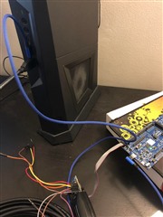
The dongle is still flashing the green LED but I cannot detect a serial port anymore. Instead, I can only see the two j-link virtual ports. None of them is printing any debug logs. There's also RTT logging feature on the VS code and when it's selected I get this pop up and choose the right board as shown. I can see the green LED on DK board flashing very fast although I have no idea why is that.
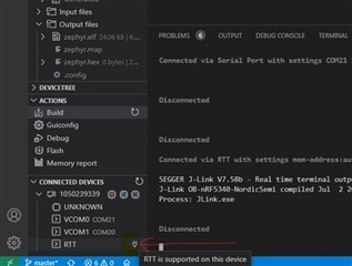
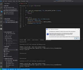
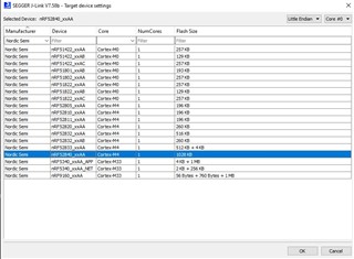
However, nothing is still printed.
My DK board is nRF52840_xxAA_Rev3(as seen on the programmer app). I can see the SB19 pad beside the DEBUG OUT header on the DK board but this post states it doesn't need to be soldered to use.
Also, I'm seeing both boards on the programmer which sounds wrong.
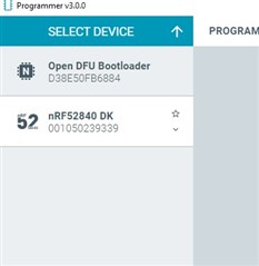
I'm sure I'm missing something here but can't figure out what after debugging for over 6 hours, hence seeking help.
Thanks


