Measuring Current Consumption on nRF9160 DK

Hi, 

I'm trying to measure the current consumption of the nRF9160 DK using a Nordic PPK 2 in various modes. Through reading up various documentation regarding this, I have a rough idea of how to do this, though I have a few questions:

1. By connecting the Vout and GND pins of the PPK2 in the SMU configuration as described here, I would be measuring the current consumption of the nRF9160 only. Is that right, or will I need to flip SW6 to the "right side" position in order to isolate the nRF9160 further?

2. When SW6 is set to the right position (MCU Disconnected), are the ui elements (switches, led, button) disconnected as well? 

3. I read that it is recommended to use the "UDP" sample here to measure the current consumption of the DK in various modes of operation (transmitting data, PSM, eDRX, etc.) but I was wondering if there were more specific guides regarding getting everything set up, such as which udp ip address to use (Should I connect it to nRF Cloud maybe?). If I were to just set it as some random ip address, would it matter in terms of power consumption that no one at the other end will be receiving those packets? 

4. How should I implement functionality of the ui elements on board the nRF9160 DK? Is there a sample that does something whenever a button is pushed or a switch is flipped for reference? I understand that in the asset_tracker_v2 sample application, there is a dedicated ui module that handles button presses and what not, should I just try to adapt that over to my program? 

Many Thanks in advance!

  • Hi,

    1. By connecting the Vout and GND pins of the PPK2 in the SMU configuration as described here, I would be measuring the current consumption of the nRF9160 only. Is that right, or will I need to flip SW6 to the "right side" position in order to isolate the nRF9160 further?

    No modifications to the DK are needed, and SW6 can be left in the default position. Ref:

     RE: Rerouting AT interface for power measurement using external supply 

    2. When SW6 is set to the right position (MCU Disconnected), are the ui elements (switches, led, button) disconnected as well? 

    No

    3. I read that it is recommended to use the "UDP" sample here to measure the current consumption of the DK in various modes of operation (transmitting data, PSM, eDRX, etc.) but I was wondering if there were more specific guides regarding getting everything set up, such as which udp ip address to use (Should I connect it to nRF Cloud maybe?). If I were to just set it as some random ip address, would it matter in terms of power consumption that no one at the other end will be receiving those packets?

    The UDP sample is already configured with e.g. an UDP server IP address. If you want to change the configuration, then here are the Kconfigs for the sample: https://github.com/nrfconnect/sdk-nrf/blob/v1.9.2/samples/nrf9160/udp/Kconfig

    4. How should I implement functionality of the ui elements on board the nRF9160 DK? Is there a sample that does something whenever a button is pushed or a switch is flipped for reference? I understand that in the asset_tracker_v2 sample application, there is a dedicated ui module that handles button presses and what not, should I just try to adapt that over to my program? 

    Depends on what you want to do, but using the DK Buttons and LEDs library might be better and easier. It's used in e.g. the mqtt_simple sample: https://github.com/nrfconnect/sdk-nrf/blob/v2.0.2/samples/nrf9160/mqtt_simple/src/main.c

  • Hi, many thanks for your responses, and they are extremely helpful. I've been following the article you referenced (here) and have managed to get close to the given value of ~3.3uA when the nRF9160 is in PSM mode. However I was wondering how I might get an estimate for the charge supplied when the nRF9160 is making its data transmission to the UDP server? 

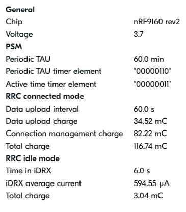
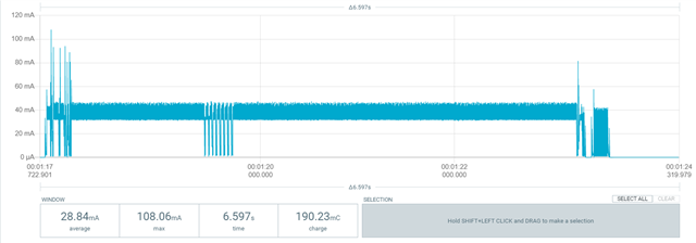
    For example, using the Online Power Profiler, the value given was approximately 116 mC but the actual value measured is closer to 190 mC.

    Online PPK result:

    Result from PPK2:

    I was just wondering if it's possible to get a sanity check as to whether or not the values I've obtained are in the ballpark or is something off about my measurements. Thanks.

  • Hi,

    Tester013 said:
    I was just wondering if it's possible to get a sanity check as to whether or not the values I've obtained are in the ballpark or is something off about my measurements. Thanks.

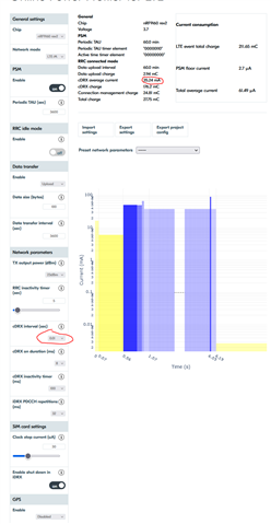
    It looks correct. Looking at your plot, it does not seem to enter connected DRX, but keeps RX on the entire time. You can simulate this by setting cDRX interval to 10ms, like this:

    You will then see that cDRX(RRC connected) average current is around 35mA, which is about what you have in your PPK plot.

Related