I am trying to use a SPI bus with three MAX3109 chips attached to give me 6 UARTS. My overlay is defined as follows:
&spi1 {
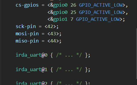
cs-gpios = <&gpio1 13 GPIO_ACTIVE_LOW>,
<&gpio1 14 GPIO_ACTIVE_LOW>,
<&gpio1 15 GPIO_ACTIVE_LOW>;
status = "okay";
sck-pin = <42>;
mosi-pin = <43>;
miso-pin = <44>;
irda_uart0: irda_uart@0 {
compatible = "spi-device";
reg = <0>;
status = "okay";
label = "IRDA_UART0";
spi-max-frequency = < 2000000 >;
};
irda_uart1: irda_uart@1 {
compatible = "spi-device";
reg = <1>;
status = "okay";
label = "IRDA_UART1";
spi-max-frequency = < 2000000 >;
};
irda_uart2: irda_uart@2 {
compatible = "spi-device";
reg = <2>;
status = "okay";
label = "IRDA_UART2";
spi-max-frequency = < 2000000 >;
};
};
I then initialize the SPI configuration to test one of the devices as:
const struct spi_cs_control *cs_pin = SPI_CS_CONTROL_PTR_DT(DT_NODELABEL(irda_uart2), 2);
static const struct spi_config spi_cfg = {
.operation = SPI_WORD_SET(8) | SPI_TRANSFER_MSB |
SPI_MODE_CPOL | SPI_MODE_CPHA,
.frequency = 2000000,
.slave = 0,
.cs = &cs_pin,
};
If I then call the following:
err = spi_transceive(spi_dev, &spi_cfg, &tx, &rx);
I can see on the scope that I have lost control of the SPI lines completely. However, if I comment out the cs pin assignment in the configuration - i.e.:
static const struct spi_config spi_cfg = {
.operation = SPI_WORD_SET(8) | SPI_TRANSFER_MSB |
SPI_MODE_CPOL | SPI_MODE_CPHA,
.frequency = 2000000,
.slave = 0,
// .cs = &cs_pin,
};
With no other changes to the code, I recompile and flash the device. Now I can see the CLK and MOSI lines exactly as expected, but of course I don't have the CS line working. I suppose I could just bit-bang the CS lines with GPIO calls, but why doesn't this arrangement work?
Thanks,
Jamie