NRF52832 (on BMD-350 Module) SWD not connecting...

I'm having no luck in getting JLinkExe or nrfjprog to see my BMD-350 device on my custom PCB. 

I have read though all the threads here that reference similar issues and have verified all of the following:

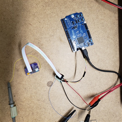
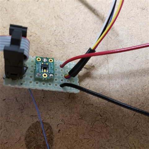
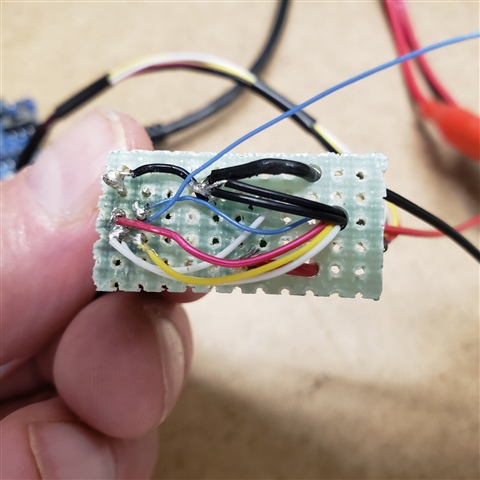
* Connections to SWCLK and SWDIO are made properly and have no pullup/pulldown resistors.

* The device is remotely powered

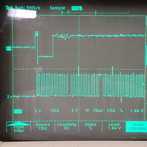
* The signals on SWCLK and SWDIO are there and look to be the proper levels.

* The device itself works - it has factory firmware that advertises services (RigDFU etc.) on BLE

I have tried both a Segger JLink as well as the using the development board programmer via the 10

pin connector.

There has to be something basic I am missing.  Below are a
PDF of the device schematic and the log.log output from nrfjprog -f nrf52 --recover

I'm doing the development in Linux, and have had no problem in connecting to the development board.

I've also asked for help from the manufacturer, UBlox, but have heard nothing back from them.

Any pointers here would be greatly appreciated.

-Glenn

6648.log.logSG_Bluetooth_4-Layer.pdf

Parents
  • Hi there,

    The schematics looks ok. 

    1. Exactly what voltage do you measure on VDD, GND and RESET pin?
    2. Have you tried omitting the regulator stage and power the board directly from a bench top supply? 
    3. Do you see this issue on all of your samples? 
    4. Thank you for including the log from nrfjprog --recover. But could you also specify what error message that is reported by the program when you just run nrfjprog --recover? 

    regards

    Jared 

  • Hi Jared,

    Thanks for responding.

     - The voltages on the board are:

       * VDD - 3.28V

       * GND - .009V

       * nRESET - 3.28V

    Under test, I am powering the board over the SWD cable with a bench power supply into a 3.3V regulator. 

    I've tried a couple of the BMD-350s, and they all seem to give the same results

    One thing I noticed when looking at a couple schematics I found for the Thingy devices is that you use a 4.6 uF capacitor after the regulator - I have just a 1uF on my board.  I was going to try putting a 4.7uF in its place but have not yet done so.

    I've attached the output from nrfjprog --recover:

    ERROR: Unable to connect to a debugger.
    ERROR: JLinkARM DLL reported an error. Try again. If error condition
    ERROR: persists, run the same command again with argument --log, contact Nordic
    ERROR: Semiconductor and provide the generated log.log file to them.
    NOTE: For additional output, try running again with logging enabled (--log).
    NOTE: Any generated log error messages will be displayed.


  • Jared,

    Sorry it took me a bit to get back to you today - other work intruded.

    Here's where I'm at.

    I re-double-checked the SWCLK and SWDIO and verified that they were going to the appropriate places.  Just to be totally sure, I swapped them anyway and ended up with the same results.  I then swapped them back to the original connections.

    I put a scope on the SWCLK and SWDIO lines and again verified that I had 0 to ~= 3.3V signals when issuing commands from nrfjprog or JLinkExe.  The fact that I get appropriate level signals would seem to indicate that they are indeed being connected to the BMD-350, since the pull-up resistors are on the chip.

    I also verified that SWO was not connected to GROUND (see my other reply).

    I'm going to build up another board or two and try those.

    Here's a shot of the scope just because it's handy - SWCLK on the bottom, SWDIO on top.   There's a little noise on the DIO line I see at the start of the pulse.  Certainly might be getting a little crosstalk between that and the SWCLK.  I didn't do anything special with the wires between the device and the perfboard.

  • Aye, I have the GND_DETECT and VCC lines connected.  When I just connect to the Dev_Kit, the tools work fine.  In fact, I just erased some test code I had loaded on the Dev_Kit because I didn't have the target board powered up.  When all the connections are there the tools refuse to talk to the target board.

    I've tried a JLink and gotten the same results.

    It's got to be something stupid I'm missing - some pin that I've connected improperly or something.

    The Dev_Kit is the Ublox BMD-350-EVAL - pretty much the same as the Rigol or regular Nordic DK from what I can tell - same 10 pin connector and such.

    Thanks for the suggestions :)

  • Idle thought: Try disconnecting Batt_Sense. It will phantom power the BMD350 and prevent the hardware reset functioning properly (internal reset, not pin reset) on power up/down. The reason is the slow startup of the LDOs driving the load capacitance so VCC comes up after io pin has powered the die via internal schottky protection diodes.. as little as 1uA can do this ..

    .. also does the op-amp have its power rails connected?

  • Interesting thoughts.  Yes, the OP-AMP is powered.  I can just pull that, and pull R7 as well as a test. 

    The OP-AMP is going to have an output voltage as well, seeing as the bridge circuit is not complete.

    Thanks again.

  • No joy Disappointed

    I pulled R7 and was able to lift a trace to disconnect the OP-AMP - neither seemed to have any effect.

    Stubborn little bugger.

Reply Children
Related