How to define SPI outputs as "HighDrive" (H0H1) outputs in a overlay file

Hello,

I want to define SPI outputs as highdrive outputs in a overlay file.

I know how to do this in the code:

const nrf_gpio_pin_drive_t SpiPinDrive = NRF_GPIO_PIN_H0H1;
nrf_gpio_reconfigure(NRF_GPIO_PIN_MAP(1, 12), NULL, NULL, NULL, &SpiPinDrive, NULL);   // CS
nrf_gpio_reconfigure(NRF_GPIO_PIN_MAP(1, 13), NULL, NULL, NULL, &SpiPinDrive, NULL);   // CLK
nrf_gpio_reconfigure(NRF_GPIO_PIN_MAP(1, 14), NULL, NULL, NULL, &SpiPinDrive, NULL);   // MOSI

But I want to do this in this overlay file:

&pinctrl {
	spi4_default: spi4_default {
		group1 {
			psels = <NRF_PSEL(SPIM_SCK, 1, 13)>,     // CLK:  P1.13 - Pin 6
					<NRF_PSEL(SPIM_MOSI, 1, 14)>,    // MOSI: P1.14 - Pin 5
					<NRF_PSEL(SPIM_MISO, 1, 15)>;    // MISO: P1.15 - Pin 2					
		};
	};

	spi4_sleep: spi4_sleep {
		group1 {
			psels = <NRF_PSEL(SPIM_SCK, 1, 13)>,     // CLK:  P1.13 - Pin 6
					<NRF_PSEL(SPIM_MOSI, 1, 14)>,    // MOSI: P1.14 - Pin 5
					<NRF_PSEL(SPIM_MISO, 1, 15)>;    // MISO: P1.15 - Pin 2
			low-power-enable;
		};
	};
};

my_spi4: &spi4 {
	compatible = "nordic,nrf-spim";
	status = "okay";
	pinctrl-0 = <&spi4_default>;
	pinctrl-1 = <&spi4_sleep>;
	cs-gpios = <&gpio1 12 GPIO_ACTIVE_LOW>;  // CS: P 1.12 - Pin 1
  m25p40: M25P40v@0 {
		compatible = "jedec,spi-nor";
		label = "M25P40";
		reg = < 0 >;
		spi-max-frequency = < 40000000 >;
		size = < 0x4000000 >;
		jedec-id = [ C2 20 13 ];
	};  
};

How do I have to modify the overlay file to achieve this ?

I am using SDK 2.0.0 & nRF5340-DK.

Thank you !

Best regards,

Georg

  • Hi,

    Try adding this line to the group1 node:

    nordic,drive-mode = <NRF_DRIVE_H0H1>;

  • Hello Oivind,

    thank you for your answer,

    It works for SPIM_SCK and SPIM_MOSI but how can I do it  for the CS  (cs-gpios)

    Best regards,

    Georg

  • Hello again,

    when looking a little bit deeper it seems not to work.

    With the follwing sequence I expect to configure P1.13 and

    P1.14 as high-drive outputs (H0H1):

    :

    ...
    
    &pinctrl {
    	spi4_default: spi4_default {
    		group1 {
    			psels = <NRF_PSEL(SPIM_SCK, 1, 13)>,         // CLK:  P1.13 - lila  - Pin 6
    					<NRF_PSEL(SPIM_MOSI, 1, 14)>;        // MOSI: P1.14 - grün  - Pin 5		
    			nordic,drive-mode = <NRF_DRIVE_H0H1>;
    		};
    		group2 {
    			psels =	<NRF_PSEL(SPIM_MISO, 1, 15)>;        // MISO: P1.15 - weiss - Pin 2			
    		};
    	};
    ...

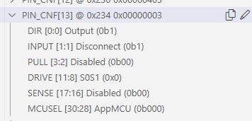
    I stopped teh debugger at the beginning of main and then I see:

    P1.13 ist confgured as S0S1 and not as H0H1

    P1.13 ist confgured as S0S1 and not as H0H1

    Best regards,

    Georg

  • I'll look into this, but are you trying to use the 32Mbps spi? If so, you must use pins P0.08-P0.12.

    https://infocenter.nordicsemi.com/index.jsp?topic=%2Fps_nrf5340%2Fchapters%2Fpin.html&cp=3_0_0_8_0

    I checked the driver, and it automatically sets the drive strength to H0H1 if you are using the spi4, set to 32M on the appropriate pins. Otherwise it will set the drive strength to S0S1.

  • Hello,

    I do not need the 32Mhz but I want to use the GPIOs as defined P1.12, P1.13,...

    I changed the SPI4 to SPI2 now the highdrive configuration works for CLK, MOSI, and MISO.

    But I want also to configure the CS (P1.12) as an  H1H0 output.

    How can I do this in the overlay ?

    Here is my current overlay:

    // To get started, press Ctrl+Space to bring up the completion menu and view the available nodes.
    
    // You can also use the buttons in the sidebar to perform actions on nodes.
    // Actions currently available include:
    
    // * Enabling / disabling the node
    // * Adding the bus to a bus
    // * Removing the node
    // * Connecting ADC channels
    
    // For more help, browse the DeviceTree documentation at https://docs.zephyrproject.org/latest/guides/dts/index.html
    // You can also visit the nRF DeviceTree extension documentation at https://nrfconnect.github.io/vscode-nrf-connect/devicetree/nrfdevicetree.html
    &pinctrl {
    	spi2_default: spi2_default {
    		group1 {
    			psels = <NRF_PSEL(SPIM_SCK, 1, 13)>,         // CLK:  P1.13 - lila  - Pin 6
    					    <NRF_PSEL(SPIM_MOSI, 1, 14)>;        // MOSI: P1.14 - grün  - Pin 5
    			nordic,drive-mode = <NRF_DRIVE_H0H1>;
    		};
    		group2 {
    			psels =	<NRF_PSEL(SPIM_MISO, 1, 15)>;        // MISO: P1.15 - weiss - Pin 2	
    		};
    	};
    
    	spi2_sleep: spi2_sleep {
    		group1 {
    			psels = <NRF_PSEL(SPIM_SCK, 1, 13)>,         // CLK:  P1.13 - lila  - Pin 6
    						  <NRF_PSEL(SPIM_MOSI, 1, 14)>,        // MOSI: P1.14 - grün  - Pin 5
    							<NRF_PSEL(SPIM_MISO, 1, 15)>;        // MISO: P1.15 - weiss - Pin 2
    			low-power-enable;
    		};
    	};
    };
    
    &spi2 {
    	compatible = "nordic,nrf-spim";
    	status = "okay";
    	pinctrl-0 = <&spi2_default>;
    	pinctrl-1 = <&spi2_sleep>;
    	cs-gpios = <&gpio1 12 GPIO_ACTIVE_LOW >;    // CS: P 1.12 - orange - Pin 1
      m25p40: M25P40v@0 {
    		compatible = "jedec,spi-nor";
    		label = "M25P40";
    		reg = < 0 >;
    		spi-max-frequency = < 40000000 >;
    		size = < 0x4000000 >;
    		jedec-id = [ C2 20 13 ];
    	};  
    };

    Best regards,

    Georg

Related