How to define SPI outputs as "HighDrive" (H0H1) outputs in a overlay file

Hello,

I want to define SPI outputs as highdrive outputs in a overlay file.

I know how to do this in the code:

const nrf_gpio_pin_drive_t SpiPinDrive = NRF_GPIO_PIN_H0H1;
nrf_gpio_reconfigure(NRF_GPIO_PIN_MAP(1, 12), NULL, NULL, NULL, &SpiPinDrive, NULL);   // CS
nrf_gpio_reconfigure(NRF_GPIO_PIN_MAP(1, 13), NULL, NULL, NULL, &SpiPinDrive, NULL);   // CLK
nrf_gpio_reconfigure(NRF_GPIO_PIN_MAP(1, 14), NULL, NULL, NULL, &SpiPinDrive, NULL);   // MOSI

But I want to do this in this overlay file:

&pinctrl {
	spi4_default: spi4_default {
		group1 {
			psels = <NRF_PSEL(SPIM_SCK, 1, 13)>,     // CLK:  P1.13 - Pin 6
					<NRF_PSEL(SPIM_MOSI, 1, 14)>,    // MOSI: P1.14 - Pin 5
					<NRF_PSEL(SPIM_MISO, 1, 15)>;    // MISO: P1.15 - Pin 2					
		};
	};

	spi4_sleep: spi4_sleep {
		group1 {
			psels = <NRF_PSEL(SPIM_SCK, 1, 13)>,     // CLK:  P1.13 - Pin 6
					<NRF_PSEL(SPIM_MOSI, 1, 14)>,    // MOSI: P1.14 - Pin 5
					<NRF_PSEL(SPIM_MISO, 1, 15)>;    // MISO: P1.15 - Pin 2
			low-power-enable;
		};
	};
};

my_spi4: &spi4 {
	compatible = "nordic,nrf-spim";
	status = "okay";
	pinctrl-0 = <&spi4_default>;
	pinctrl-1 = <&spi4_sleep>;
	cs-gpios = <&gpio1 12 GPIO_ACTIVE_LOW>;  // CS: P 1.12 - Pin 1
  m25p40: M25P40v@0 {
		compatible = "jedec,spi-nor";
		label = "M25P40";
		reg = < 0 >;
		spi-max-frequency = < 40000000 >;
		size = < 0x4000000 >;
		jedec-id = [ C2 20 13 ];
	};  
};

How do I have to modify the overlay file to achieve this ?

I am using SDK 2.0.0 & nRF5340-DK.

Thank you !

Best regards,

Georg

Parents Reply Children
  • Hello,

    I do not need the 32Mhz but I want to use the GPIOs as defined P1.12, P1.13,...

    I changed the SPI4 to SPI2 now the highdrive configuration works for CLK, MOSI, and MISO.

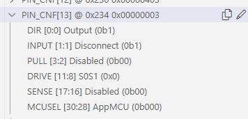
    But I want also to configure the CS (P1.12) as an  H1H0 output.

    How can I do this in the overlay ?

    Here is my current overlay:

    // To get started, press Ctrl+Space to bring up the completion menu and view the available nodes.
    
    // You can also use the buttons in the sidebar to perform actions on nodes.
    // Actions currently available include:
    
    // * Enabling / disabling the node
    // * Adding the bus to a bus
    // * Removing the node
    // * Connecting ADC channels
    
    // For more help, browse the DeviceTree documentation at https://docs.zephyrproject.org/latest/guides/dts/index.html
    // You can also visit the nRF DeviceTree extension documentation at https://nrfconnect.github.io/vscode-nrf-connect/devicetree/nrfdevicetree.html
    &pinctrl {
    	spi2_default: spi2_default {
    		group1 {
    			psels = <NRF_PSEL(SPIM_SCK, 1, 13)>,         // CLK:  P1.13 - lila  - Pin 6
    					    <NRF_PSEL(SPIM_MOSI, 1, 14)>;        // MOSI: P1.14 - grün  - Pin 5
    			nordic,drive-mode = <NRF_DRIVE_H0H1>;
    		};
    		group2 {
    			psels =	<NRF_PSEL(SPIM_MISO, 1, 15)>;        // MISO: P1.15 - weiss - Pin 2	
    		};
    	};
    
    	spi2_sleep: spi2_sleep {
    		group1 {
    			psels = <NRF_PSEL(SPIM_SCK, 1, 13)>,         // CLK:  P1.13 - lila  - Pin 6
    						  <NRF_PSEL(SPIM_MOSI, 1, 14)>,        // MOSI: P1.14 - grün  - Pin 5
    							<NRF_PSEL(SPIM_MISO, 1, 15)>;        // MISO: P1.15 - weiss - Pin 2
    			low-power-enable;
    		};
    	};
    };
    
    &spi2 {
    	compatible = "nordic,nrf-spim";
    	status = "okay";
    	pinctrl-0 = <&spi2_default>;
    	pinctrl-1 = <&spi2_sleep>;
    	cs-gpios = <&gpio1 12 GPIO_ACTIVE_LOW >;    // CS: P 1.12 - orange - Pin 1
      m25p40: M25P40v@0 {
    		compatible = "jedec,spi-nor";
    		label = "M25P40";
    		reg = < 0 >;
    		spi-max-frequency = < 40000000 >;
    		size = < 0x4000000 >;
    		jedec-id = [ C2 20 13 ];
    	};  
    };

    Best regards,

    Georg

  • I'll look into why it works differently on SPI4.

    May I ask why you need the CS pin to be high drive? Unless I am missing something, it shouldn't be needed.

  • I wired an SPI Flash (M25P40) to the SDK. And  I had lot of of problems with wrong data until I changed the CLK to H0H1. So I decided to change all SPI Outputs to H01H1 to avoid furure problems. 

  • Ok, on the other pins that makes sense, but since the CS pin will at most be 1/8 or 1/16 the frequency of the other pins, I believe it should be fine at standard drive.

  • it seems that it is not possible to configure the CS signal as an H0H1 output in an overlay file. Thank you for your support.

    Best regards,

    Georg

Related