PWM Sequence from HAL to NRFX

Hello

I am trying to change the code from the HAL code up to NRFX in order to make it event-based instead of using infinite while loops. 

I am using 52840 on a custom PCA with goal in mind to create a half-duplex-half-UART communication.

Working with HAL drivers, the code works as intended, but it is not optimized and is very power hungry for our needs. 

The HAL Setup and sending of the message (Byte by byte, each byte 10 bits at a time (Start - 8xData - Stop)): 

TxSetup()
{
    NRF_P0->DIRSET = ((1UL) << PIN_NEG); // PIN_NEG as output
    NRF_P0->OUTCLR = ((1UL) << PIN_NEG); // initial LOW on PIN_NEG

    NRF_P0->DIRSET = ((1UL) << PIN_POS); // PIN_POS as output
    NRF_P0->OUTSET = ((1UL) << PIN_POS); // initial HIGH on PIN_POS

    CounterTopRegister = F_CLK / F_PWM; // F_CLK = 16000000
    cyclesPerBit = F_PWM / LL_BAUDRATE; // F_PWM = 32400 ; LL_BAUDRATE = 1200
    P_PWM_HIGH = CounterTopRegister;
    P_PWM_LOW = (int)(0.5 * CounterTopRegister);
    N_PWM_HIGH = P_PWM_HIGH + 0x8000;
    N_PWM_LOW = P_PWM_LOW + 0x8000;

    NRF_PWM2->PSEL.OUT[0] = (PIN_POS << PWM_PSEL_OUT_PIN_Pos) | (PIN_POS << PWM_PSEL_OUT_PORT_Pos) | (PWM_PSEL_OUT_CONNECT_Connected << PWM_PSEL_OUT_CONNECT_Pos);
    NRF_PWM2->PSEL.OUT[1] = (PIN_NEG << PWM_PSEL_OUT_PIN_Pos) | (PIN_NEG << PWM_PSEL_OUT_PORT_Pos) | (PWM_PSEL_OUT_CONNECT_Connected << PWM_PSEL_OUT_CONNECT_Pos);
    NRF_PWM2->MODE = (PWM_MODE_UPDOWN_Up << PWM_MODE_UPDOWN_Pos);
    NRF_PWM2->PRESCALER = (PWM_PRESCALER_PRESCALER_DIV_1 << PWM_PRESCALER_PRESCALER_Pos);
    NRF_PWM2->COUNTERTOP = (CounterTopRegister << PWM_COUNTERTOP_COUNTERTOP_Pos);
    NRF_PWM2->LOOP = (0 << PWM_LOOP_CNT_Pos);
    NRF_PWM2->DECODER = (PWM_DECODER_LOAD_Individual << PWM_DECODER_LOAD_Pos) | (PWM_DECODER_MODE_RefreshCount << PWM_DECODER_MODE_Pos);
    NRF_PWM2->SEQ[0].PTR = ((uint32_t)(initialSequence) << PWM_SEQ_PTR_PTR_Pos);

    NRF_PWM2->SEQ[0].CNT = 44;
    NRF_PWM2->SEQ[0].REFRESH = cyclesPerBit - 1;
    NRF_PWM2->SEQ[0].ENDDELAY = 0;
}

void TxWrite(uint8_t txVal)
{
    int i;
    // Generate the Startbit (LOW)
    initialSequence[0] = P_PWM_LOW;
    initialSequence[1] = N_PWM_LOW;
    initialSequence[2] = 0;
    initialSequence[3] = 0;
    // Generate the 8 databits
    for (i = 1; i < 9; i++)
    {
        if (txVal & 1)
        {
            // Bit is HIGH
            initialSequence[4 * i + 0] = P_PWM_HIGH;
            initialSequence[4 * i + 1] = N_PWM_HIGH;
        }
        else
        {
            // Bit is LOW
            initialSequence[4 * i + 0] = P_PWM_LOW;
            initialSequence[4 * i + 1] = N_PWM_LOW;
        }
        initialSequence[4 * i + 2] = 0;
        initialSequence[4 * i + 3] = 0;
        txVal = txVal >> 1;
    }

    // Generate the Stopbit (HIGH)
    initialSequence[36] = P_PWM_HIGH;
    initialSequence[37] = N_PWM_HIGH;
    initialSequence[38] = 0;
    initialSequence[39] = 0;
    initialSequence[40] = P_PWM_HIGH;
    initialSequence[41] = N_PWM_HIGH;
    initialSequence[42] = 0;
    initialSequence[43] = 0;

    NRF_PWM2->ENABLE = (PWM_ENABLE_ENABLE_Enabled << PWM_ENABLE_ENABLE_Pos);

    NRF_PWM2->TASKS_SEQSTART[0] = 1;
}

void TxWaitDone()
{

    while (NRF_PWM2->EVENTS_SEQEND[0] == 0)
        ;
    NRF_PWM2->EVENTS_SEQEND[0] = 0;
}

void TxStop()
{

    NRF_PWM2->TASKS_STOP = 1;

    while (NRF_PWM2->EVENTS_STOPPED == 0)
        ;
    NRF_PWM2->EVENTS_STOPPED = 0;

    NRF_PWM2->ENABLE = (PWM_ENABLE_ENABLE_Disabled << PWM_ENABLE_ENABLE_Pos);
}


WriteMessage(uint8_t *msg, uint8_t len)
{
    nrfx_lpcomp_disable();
    NRFX_IRQ_DISABLE(SAADC_IRQn);
    for (int i = 0; i < len; i++)
    {
        TxWrite(msg[i]);
        TxWaitDone();
        TxStop();
    }
    lpcomp_event_count = 0;
    is_carrier_found = 0;
    NRFX_IRQ_ENABLE(COMP_LPCOMP_IRQn);
    nrfx_lpcomp_enable();
    return 0;
}

The issue with this approach, again, is the while loops that, among other issues, can sometimes get stuck and hang the rest of the process. 

The actual issue rewriting this with NRFX drivers is the fact that I cannot, for the life of me, figure out how to write out my "initialSequence." I can get the PWM to toggle on or off, but not actually make it do that in sequence as I need it to. I tried following a few examples I found on Devzone, but nothing concrete enough to help me with my issue. 

The HAL Implementation repeats every 100 milliseconds, so the NRFX one should be able to match that. If anyone has an idea of how to write this using the NRFX drivers, or to point me in the direction of a set-up example, I'd be very grateful. 
To add to this: The idea is for this code to run along with a Zephyr based system that runs the rest of the functionality of the board (Thus why we're trying to make it event based as opposed to current implementation).

Thank you in advanced for response. If you need any more information, please ask. 

EDIT: Added the missing code that was calling the TX sequence in order. (Write, Wait, Stop)

Parents
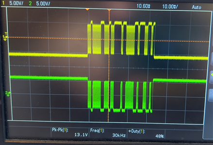
  •    I feel I should add the way the signal looks as well with HAL(first picture) and   NRFX (Second picture)
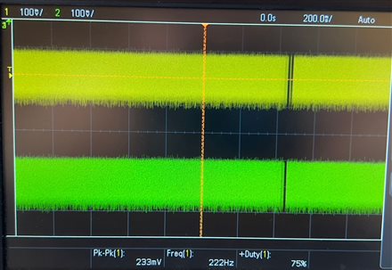
  • Not sure the api drivers correctly handle the pins, but looking at the 'scope seems the pins aren't configured so try adding this after the init:

    // Boost differential pwm driver pins to high drive
    nrf_gpio_cfg(PIN_POS, NRF_GPIO_PIN_DIR_OUTPUT, NRF_GPIO_PIN_INPUT_DISCONNECT, NRF_GPIO_PIN_NOPULL, NRF_GPIO_PIN_H0H1, NRF_GPIO_PIN_NOSENSE);
    nrf_gpio_cfg(PIN_NEG, NRF_GPIO_PIN_DIR_OUTPUT, NRF_GPIO_PIN_INPUT_DISCONNECT, NRF_GPIO_PIN_NOPULL, NRF_GPIO_PIN_H0H1, NRF_GPIO_PIN_NOSENSE);
    

  • Ok couldn't resist testing further, so here's a working example using the 4-byte data you specified:

    // PWM Half-Duplex UART - nrfx drivers
    // ===================================
    // Requirements
    //  10 bit bytes (Start - 8xData - Stop)
    //  single char or burst (packet) transmission
    //  Differential output using 2 pins
    //  No level change on pins outside transmitted data to avoid spurious character detection
    #include "nrf_pwm.h"
    
    #define LL_BAUDRATE      1200
    #define F_CLK        16000000              // nRF52832/nRF52840 fixed at 16MHz
    #define F_PRESCALER  (PWM_PRESCALER_PRESCALER_DIV_1)  // Divide by 1, 16MHz clock
    #define COUNTER_TOP  ((F_CLK+(LL_BAUDRATE/2)) / LL_BAUDRATE)
    STATIC_ASSERT(COUNTER_TOP < 32768, "COUNTER_TOP value too large for 15-bit register");
    STATIC_ASSERT(COUNTER_TOP >= 3, "COUNTER_TOP value too small for correct operation");
    #define BIT_LOW               0           // Normal encoding
    #define BIT_HIGH    (COUNTER_TOP)         // Normal encoding
    //#define BIT_LOW   ((2*COUNTER_TOP)/3)   // Manchester encoding 2/3 bit
    //#define BIT_HIGH  (COUNTER_TOP/3)       // Manchester encoding 1/3 bit
    #define PWM_NEG (PIN_FEATHER_D6)          // Low level outside transmission
    #define PWM_POS (PIN_FEATHER_D9)          // High level outside transmission
    
    typedef struct TX_BYTE_T {
        nrf_pwm_values_grouped_t StartBit;
        nrf_pwm_values_grouped_t DataBits[8];
        nrf_pwm_values_grouped_t StopBit;
    } TxByte_t;
    
    TxByte_t TxPacket[4];
    const uint16_t TxPacketSize = (sizeof(TxPacket)/sizeof(uint16_t));
    
    void encodeByte(TxByte_t* pBuffer, const uint8_t ch)
    {
        // Encode byte in little-endian format with start and stop bits
        pBuffer->StartBit.group_0 = pBuffer->StartBit.group_1 = (BIT_LOW);  pBuffer->StartBit.group_0 |= 0x8000; // 0 Start bit
        pBuffer->StopBit.group_0  = pBuffer->StopBit.group_1  = (BIT_HIGH); pBuffer->StopBit.group_0  |= 0x8000; // 0 Stop bit
        for(uint32_t i=0; i<8; i++)
        {
            pBuffer->DataBits[i].group_0 = pBuffer->DataBits[i].group_1 = (((ch>>i) & 0x01) ? BIT_HIGH : BIT_LOW);
            pBuffer->DataBits[i].group_0 |= 0x8000; // inverted pin
        }
    }
    
    buildMessage(void)
    {
        TxByte_t *pTx = TxPacket;
        uint8_t STX         = 0x82;
        uint8_t signal_id   = 0x64 | 0x80;
        uint8_t data_byte_0 = 0x03 | 0x80;
        uint8_t checksum    = (signal_id) + (data_byte_0);
        checksum &= 0x7F;
        encodeByte(pTx++, STX);
        encodeByte(pTx++, signal_id);
        encodeByte(pTx++, data_byte_0);
        encodeByte(pTx++, checksum);
    }
    
    void TestPWM_Uart(void)
    {
        static nrfx_pwm_t m_pwm0 = NRFX_PWM_INSTANCE(0);
        uint32_t err_code;
        // Declare a configuration structure and use a macro to instantiate it with default parameters.
        nrfx_pwm_config_t pwm_config = NRFX_PWM_DEFAULT_CONFIG;
        //    .irq_priority = NRFX_PWM_DEFAULT_CONFIG_IRQ_PRIORITY,                  \
        //    .base_clock   = (nrf_pwm_clk_t)NRFX_PWM_DEFAULT_CONFIG_BASE_CLOCK,     \
        //    .count_mode   = (nrf_pwm_mode_t)NRFX_PWM_DEFAULT_CONFIG_COUNT_MODE,    \
        //    .top_value    = NRFX_PWM_DEFAULT_CONFIG_TOP_VALUE,                     \
        //    .load_mode    = (nrf_pwm_dec_load_t)NRFX_PWM_DEFAULT_CONFIG_LOAD_MODE, \
        //    .step_mode    = (nrf_pwm_dec_step_t)NRFX_PWM_DEFAULT_CONFIG_STEP_MODE
       static nrf_pwm_sequence_t pwm_sequence;
    
        // Override some of the default parameters:
        pwm_config.output_pins[0] = PWM_NEG | NRFX_PWM_PIN_INVERTED;
        pwm_config.output_pins[1] = NRFX_PWM_PIN_NOT_USED;
        pwm_config.output_pins[2] = PWM_POS;
        pwm_config.output_pins[3] = NRFX_PWM_PIN_NOT_USED;
    
        pwm_config.load_mode      = NRF_PWM_LOAD_GROUPED;   // 1 == 1st half word (16-bit) used in channels 0 and 1; 2nd word in channels 2 and 3
        pwm_config.base_clock     = F_PRESCALER;            // 0 == divide by 1 for 16MHz clock
        pwm_config.step_mode      = NRFX_PWM_DEFAULT_CONFIG_STEP_MODE; // 0 == Count Up
        pwm_config.top_value      = COUNTER_TOP;
    
        // Pass config structure into driver init() function
        err_code = nrfx_pwm_init(&m_pwm0, &pwm_config, NULL);
        APP_ERROR_CHECK(err_code);
        // Boost differential pwm driver pins to high drive - this is optional
        nrf_gpio_cfg(PWM_NEG, NRF_GPIO_PIN_DIR_OUTPUT, NRF_GPIO_PIN_INPUT_DISCONNECT, NRF_GPIO_PIN_NOPULL, NRF_GPIO_PIN_H0H1, NRF_GPIO_PIN_NOSENSE);
        nrf_gpio_cfg(PWM_POS, NRF_GPIO_PIN_DIR_OUTPUT, NRF_GPIO_PIN_INPUT_DISCONNECT, NRF_GPIO_PIN_NOPULL, NRF_GPIO_PIN_H0H1, NRF_GPIO_PIN_NOSENSE);
        // Encode the 4-byte test message
        buildMessage();
        pwm_sequence.values.p_grouped = (uint32_t)TxPacket;
        pwm_sequence.length           = TxPacketSize;
        pwm_sequence.repeats          = 0;
        nrfx_pwm_simple_playback(&m_pwm0, &pwm_sequence, 1, NRFX_PWM_FLAG_STOP); // Send once
        while (1)
        {
            __WFE();
        }
    }

    Usually would add an interrupt to signify end-of-transmission

  • Hi, Thank you so much for working the solution out and testing it! 
    I have adapted your solution to my code and managed to get a similar output to the one that I need. But I still have one small issue: The Frequency is ~1KHz, I need 32. 
    Duty cycle keeps varrying from 20-80% where as I need it on 50% (As fixed as possible). I've tried changing some values in the code you provided, but I'm having no luck with getting the wanted result. 
    If you have a fix for that as well, that'll have solved my issue. 
    And if not, I am beyond grateful for the help thus far, it's helped me get a little deeper understanding of how the new API is working.

  • Not sure I understand your duty cycle comments; can you sketch a wavefor of a specific character?

    The frequence is set by LL_BAUDRATE =1200, which is 1.2kHz; 32kHz is set by LL_BAUDRATE =32000

    To get crystal-stable frequency with no jitter add this code at the start:

        // Start accurate HFCLK (XOSC)
        NRF_CLOCK->TASKS_HFCLKSTART = 1;
        while (NRF_CLOCK->EVENTS_HFCLKSTARTED == 0)
            ;
        NRF_CLOCK->EVENTS_HFCLKSTARTED = 0;
    

    Standard UART:

    // Standard Uart character 0x21
    //
    //        |     |     |     |     |     |     |     |     |     |     |
    //  Idle   Start   0     1     2     3     4     5     6     7   Stop    Idle
    // -------+     +-----+                       +-----+           +-----+-------
    //        |     |     |                       |     |           |
    //        |     |     |                       |     |           |       Normal
    //        +-----+     +-----+-----+-----+-----+     +-----+-----+
    //
    //        +-----+     +-----+-----+-----+-----+     +-----+-----+
    //        |     |     |                       |     |           |       Invert
    //        |     |     |                       |     |           |
    // -------+     +-----+                       +-----+           +-----+-------

Reply
  • Not sure I understand your duty cycle comments; can you sketch a wavefor of a specific character?

    The frequence is set by LL_BAUDRATE =1200, which is 1.2kHz; 32kHz is set by LL_BAUDRATE =32000

    To get crystal-stable frequency with no jitter add this code at the start:

        // Start accurate HFCLK (XOSC)
        NRF_CLOCK->TASKS_HFCLKSTART = 1;
        while (NRF_CLOCK->EVENTS_HFCLKSTARTED == 0)
            ;
        NRF_CLOCK->EVENTS_HFCLKSTARTED = 0;
    

    Standard UART:

    // Standard Uart character 0x21
    //
    //        |     |     |     |     |     |     |     |     |     |     |
    //  Idle   Start   0     1     2     3     4     5     6     7   Stop    Idle
    // -------+     +-----+                       +-----+           +-----+-------
    //        |     |     |                       |     |           |
    //        |     |     |                       |     |           |       Normal
    //        +-----+     +-----+-----+-----+-----+     +-----+-----+
    //
    //        +-----+     +-----+-----+-----+-----+     +-----+-----+
    //        |     |     |                       |     |           |       Invert
    //        |     |     |                       |     |           |
    // -------+     +-----+                       +-----+           +-----+-------

Children
No Data
Related