NCS v2.0.0 - aws_iot sample - No UART output when using an overlay file

Hi,

I'm working with the NCS v2.0.0 - aws_iot sample and an nRF9160 on a custom board.

I have tested the aws_iot sample on an nRF9160DK and have confirmed that it works.

It appears that when I attempt to use an overlay file to change the TX and RX pins of UART_0, the UART output stops working.

I have tested this overlay file using hello world sample on my custom board and it outputs as expected.

I have attached my overlay file below, could you let me know what might be happening?

Thanks,

Alvin

6431.nrf9160dk_nrf9160_ns.overlay

Parents
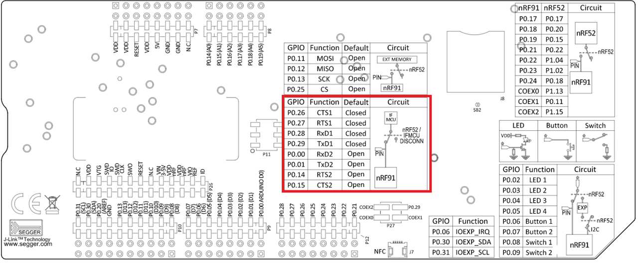
  • If you look at GPIO interfaces and Virtual COM port you can see that P0.00 and P0.01 are connected to the Interface MCU. So when changing to these pins, the output should go out to another COM port when using P0.00 and P0.01.

    I tested this myself. First I connected the nRF9160 DK to the computer, and then I ran nrfjprog --com, and got the following output:

    $ nrfjprog --com
    960013235 COM37 VCOM1
    960013235 COM38 VCOM2
    960013235 COM39 VCOM0

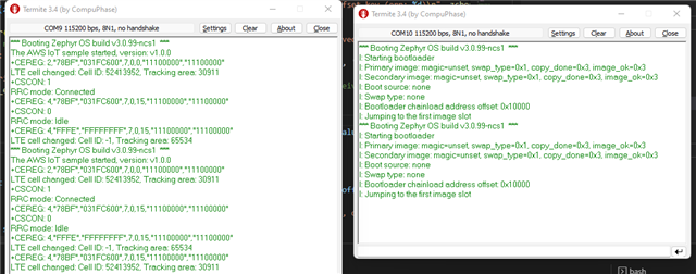
    I then tried to program the hello_world sample to the nRF9160 DK, and the UART log was output on COM39. Then I applied your overlay file, and UART log was now output on COM38. See the below image.

    Do you see the same behaviour on your side? If not, could you upload your project here?

    Best regards,

    Simon

  • Hi Simon,

    I can confirm that using the overlay file with the hello_world sample works on my custom board. I was getting UART communication on P0.00 and P0.01.

    However when I attempt to use the same overlay file on the aws_iot sample, it no longer outputs anything on the UART.

    The aws_iot sample I'm using was found in the NCS v2.0.0 toolchain nrf > samples > nrf9160 > aws_iot

    Thanks,

    Alvin

  • Did you see the bootup message *** Booting Zephyr OS build v3.1.99-ncs1 *** and nothing else after that ??

  • I tested your overlay with the aws_iot sample as well, and it worked fine:

    As you can see, the MCUboot log (which the overlay file don't apply to) outputs the log to one COM port, while the output from the aws_iot sample are ouput on another.

    • Have you done any other modifications to the aws_iot sample?
    • What nRF9160DK version are you using?
    • What terminal program are you using?
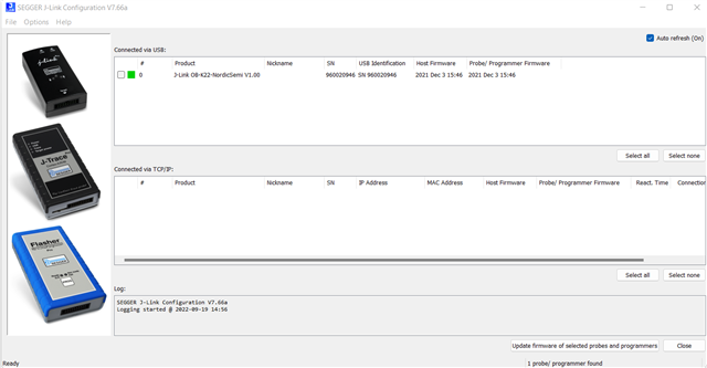
    • What firmware do you have on the Interface MCU? 

    Best regards,

    Simon 

  • That is different than what I'm experiencing - here are my observations so far. I am using NCS v2.0.0 and MFW v1.3.1. The board selected in the build configuration in Visual Studio Code is nrf9160dk_nrf9160_ns.

    I'm using nRF9160DK PCA10090 1.0.0 - Date code 2021.11

    I'm using LTE Link Monitor v2.0.2 launched from nRF Connect for Desktop v3.12.0

    Here is a screenshot of the Interface MCU firmware version

    -----

    1. Here is my output when running the aws_iot sample from NCS v2.0.0 with no changes.

    2. It looks like the application was getting stuck at "Jumping to the first image slot" and I found this thread on the forums https://devzone.nordicsemi.com/f/nordic-q-a/88878/9160dk-boot-stuck-at-jumping-to-the-first-image-slot-sample-http_update-with-ncs-2-0-0. Adding the following lines to the proj.conf file resulted in the output below. No overlay file. This seemed to work as the application was now starting.

    Added to the end of prj.conf:

    # SPM
    CONFIG_SPM=y
    CONFIG_BUILD_WITH_TFM=n

    Last lines of output - full output below (2022-09-19 aws_iot Output - SPM - No Overlay.txt)

    *** Booting Zephyr OS build v3.0.99-ncs1  ***


    The AWS IoT sample started, version: v1.0.0


    +CEREG: 90
    
    
    LTE cell changed: Cell ID: -1, Tracking area: -1

    *** Booting Zephyr OS build v3.0.99-ncs1  ***I: Starting bootloaderI: Primary image: magic=unset, swap_type=0x1, copy_done=0x3, image_ok=0x3I: Secondary image: magic=unset, swap_type=0x1, copy_done=0x3, image_ok=0x3I: Boot source: noneI: Swap type: noneI: Bootloader chainload address offset: 0x10000I: Jumping to the first image slot*** Booting Zephyr OS build v3.0.99-ncs1  ***Flash regionsDomainPermissions00 03 0x00000 0x20000 Securerwxl04 31 0x20000 0x100000 Non-SecurerwxlNon-secure callable region 0 placed in flash region 3 with size 32.SRAM regionDomainPermissions00 03 0x00000 0x08000 Securerwxl04 31 0x08000 0x40000 Non-SecurerwxlPeripheralDomainStatus00 NRF_P0               Non-SecureOK01 NRF_CLOCK            Non-SecureOK02 NRF_RTC0             Non-SecureOK03 NRF_RTC1             Non-SecureOK04 NRF_NVMC             Non-SecureOK05 NRF_UARTE1           Non-SecureOK06 NRF_UARTE2           SecureSKIP07 NRF_TWIM2            Non-SecureOK08 NRF_SPIM3            Non-SecureOK09 NRF_TIMER0           Non-SecureOK10 NRF_TIMER1           Non-SecureOK11 NRF_TIMER2           Non-SecureOK12 NRF_SAADC            Non-SecureOK13 NRF_PWM0             Non-SecureOK14 NRF_PWM1             Non-SecureOK15 NRF_PWM2             Non-SecureOK16 NRF_PWM3             Non-SecureOK17 NRF_WDT              Non-SecureOK18 NRF_IPC              Non-SecureOK19 NRF_VMC              Non-SecureOK20 NRF_FPU              Non-SecureOK21 NRF_EGU0             Non-SecureOK22 NRF_EGU1             Non-SecureOK23 NRF_EGU2             Non-SecureOK24 NRF_EGU3             Non-SecureOK25 NRF_EGU4             Non-SecureOK26 NRF_EGU5             Non-SecureOK27 NRF_DPPIC            Non-SecureOK28 NRF_REGULATORS       Non-SecureOK29 NRF_PDM              Non-SecureOK30 NRF_I2S              Non-SecureOK31 NRF_GPIOTE1          Non-SecureOKSPM: NS image at 0x20200SPM: NS MSP at 0x20014d60SPM: NS reset vector at 0x26169SPM: prepare to jump to Non-Secure image.*** Booting Zephyr OS build v3.0.99-ncs1  ***The AWS IoT sample started, version: v1.0.0+CEREG: 90LTE cell changed: Cell ID: -1, Tracking area: -1

    3. After this, I added the overlay file from above to set UART0 TX to P0.01. I connected an oscilloscope probe to P0.01 on the DK, but was unable to see any activity on this pin.

    Here is the output from this setup, I would expect to see the message "*** Booting Zephyr OS" etc show up on P0.01 like in your screenshots above, but I am seeing nothing on P0.01.

    *** Booting Zephyr OS build v3.0.99-ncs1  ***I: Starting bootloaderI: Primary image: magic=unset, swap_type=0x1, copy_done=0x3, image_ok=0x3I: Secondary image: magic=unset, swap_type=0x1, copy_done=0x3, image_ok=0x3I: Boot source: noneI: Swap type: noneI: Bootloader chainload address offset: 0x10000I: Jumping to the first image slot*** Booting Zephyr OS build v3.0.99-ncs1  ***Flash regionsDomainPermissions00 03 0x00000 0x20000 Securerwxl04 31 0x20000 0x100000 Non-SecurerwxlNon-secure callable region 0 placed in flash region 3 with size 32.SRAM regionDomainPermissions00 03 0x00000 0x08000 Securerwxl04 31 0x08000 0x40000 Non-SecurerwxlPeripheralDomainStatus00 NRF_P0               Non-SecureOK01 NRF_CLOCK            Non-SecureOK02 NRF_RTC0             Non-SecureOK03 NRF_RTC1             Non-SecureOK04 NRF_NVMC             Non-SecureOK05 NRF_UARTE1           Non-SecureOK06 NRF_UARTE2           SecureSKIP07 NRF_TWIM2            Non-SecureOK08 NRF_SPIM3            Non-SecureOK09 NRF_TIMER0           Non-SecureOK10 NRF_TIMER1           Non-SecureOK11 NRF_TIMER2           Non-SecureOK12 NRF_SAADC            Non-SecureOK13 NRF_PWM0             Non-SecureOK14 NRF_PWM1             Non-SecureOK15 NRF_PWM2             Non-SecureOK16 NRF_PWM3             Non-SecureOK17 NRF_WDT              Non-SecureOK18 NRF_IPC              Non-SecureOK19 NRF_VMC              Non-SecureOK20 NRF_FPU              Non-SecureOK21 NRF_EGU0             Non-SecureOK22 NRF_EGU1             Non-SecureOK23 NRF_EGU2             Non-SecureOK24 NRF_EGU3             Non-SecureOK25 NRF_EGU4             Non-SecureOK26 NRF_EGU5             Non-SecureOK27 NRF_DPPIC            Non-SecureOK28 NRF_REGULATORS       Non-SecureOK29 NRF_PDM              Non-SecureOK30 NRF_I2S              Non-SecureOK31 NRF_GPIOTE1          Non-SecureOKSPM: NS image at 0x20200SPM: NS MSP at 0x20014d60SPM: NS reset vector at 0x26169SPM: prepare to jump to Non-Secure image.

Reply
  • That is different than what I'm experiencing - here are my observations so far. I am using NCS v2.0.0 and MFW v1.3.1. The board selected in the build configuration in Visual Studio Code is nrf9160dk_nrf9160_ns.

    I'm using nRF9160DK PCA10090 1.0.0 - Date code 2021.11

    I'm using LTE Link Monitor v2.0.2 launched from nRF Connect for Desktop v3.12.0

    Here is a screenshot of the Interface MCU firmware version

    -----

    1. Here is my output when running the aws_iot sample from NCS v2.0.0 with no changes.

    2. It looks like the application was getting stuck at "Jumping to the first image slot" and I found this thread on the forums https://devzone.nordicsemi.com/f/nordic-q-a/88878/9160dk-boot-stuck-at-jumping-to-the-first-image-slot-sample-http_update-with-ncs-2-0-0. Adding the following lines to the proj.conf file resulted in the output below. No overlay file. This seemed to work as the application was now starting.

    Added to the end of prj.conf:

    # SPM
    CONFIG_SPM=y
    CONFIG_BUILD_WITH_TFM=n

    Last lines of output - full output below (2022-09-19 aws_iot Output - SPM - No Overlay.txt)

    *** Booting Zephyr OS build v3.0.99-ncs1  ***


    The AWS IoT sample started, version: v1.0.0


    +CEREG: 90
    
    
    LTE cell changed: Cell ID: -1, Tracking area: -1

    *** Booting Zephyr OS build v3.0.99-ncs1  ***I: Starting bootloaderI: Primary image: magic=unset, swap_type=0x1, copy_done=0x3, image_ok=0x3I: Secondary image: magic=unset, swap_type=0x1, copy_done=0x3, image_ok=0x3I: Boot source: noneI: Swap type: noneI: Bootloader chainload address offset: 0x10000I: Jumping to the first image slot*** Booting Zephyr OS build v3.0.99-ncs1  ***Flash regionsDomainPermissions00 03 0x00000 0x20000 Securerwxl04 31 0x20000 0x100000 Non-SecurerwxlNon-secure callable region 0 placed in flash region 3 with size 32.SRAM regionDomainPermissions00 03 0x00000 0x08000 Securerwxl04 31 0x08000 0x40000 Non-SecurerwxlPeripheralDomainStatus00 NRF_P0               Non-SecureOK01 NRF_CLOCK            Non-SecureOK02 NRF_RTC0             Non-SecureOK03 NRF_RTC1             Non-SecureOK04 NRF_NVMC             Non-SecureOK05 NRF_UARTE1           Non-SecureOK06 NRF_UARTE2           SecureSKIP07 NRF_TWIM2            Non-SecureOK08 NRF_SPIM3            Non-SecureOK09 NRF_TIMER0           Non-SecureOK10 NRF_TIMER1           Non-SecureOK11 NRF_TIMER2           Non-SecureOK12 NRF_SAADC            Non-SecureOK13 NRF_PWM0             Non-SecureOK14 NRF_PWM1             Non-SecureOK15 NRF_PWM2             Non-SecureOK16 NRF_PWM3             Non-SecureOK17 NRF_WDT              Non-SecureOK18 NRF_IPC              Non-SecureOK19 NRF_VMC              Non-SecureOK20 NRF_FPU              Non-SecureOK21 NRF_EGU0             Non-SecureOK22 NRF_EGU1             Non-SecureOK23 NRF_EGU2             Non-SecureOK24 NRF_EGU3             Non-SecureOK25 NRF_EGU4             Non-SecureOK26 NRF_EGU5             Non-SecureOK27 NRF_DPPIC            Non-SecureOK28 NRF_REGULATORS       Non-SecureOK29 NRF_PDM              Non-SecureOK30 NRF_I2S              Non-SecureOK31 NRF_GPIOTE1          Non-SecureOKSPM: NS image at 0x20200SPM: NS MSP at 0x20014d60SPM: NS reset vector at 0x26169SPM: prepare to jump to Non-Secure image.*** Booting Zephyr OS build v3.0.99-ncs1  ***The AWS IoT sample started, version: v1.0.0+CEREG: 90LTE cell changed: Cell ID: -1, Tracking area: -1

    3. After this, I added the overlay file from above to set UART0 TX to P0.01. I connected an oscilloscope probe to P0.01 on the DK, but was unable to see any activity on this pin.

    Here is the output from this setup, I would expect to see the message "*** Booting Zephyr OS" etc show up on P0.01 like in your screenshots above, but I am seeing nothing on P0.01.

    *** Booting Zephyr OS build v3.0.99-ncs1  ***I: Starting bootloaderI: Primary image: magic=unset, swap_type=0x1, copy_done=0x3, image_ok=0x3I: Secondary image: magic=unset, swap_type=0x1, copy_done=0x3, image_ok=0x3I: Boot source: noneI: Swap type: noneI: Bootloader chainload address offset: 0x10000I: Jumping to the first image slot*** Booting Zephyr OS build v3.0.99-ncs1  ***Flash regionsDomainPermissions00 03 0x00000 0x20000 Securerwxl04 31 0x20000 0x100000 Non-SecurerwxlNon-secure callable region 0 placed in flash region 3 with size 32.SRAM regionDomainPermissions00 03 0x00000 0x08000 Securerwxl04 31 0x08000 0x40000 Non-SecurerwxlPeripheralDomainStatus00 NRF_P0               Non-SecureOK01 NRF_CLOCK            Non-SecureOK02 NRF_RTC0             Non-SecureOK03 NRF_RTC1             Non-SecureOK04 NRF_NVMC             Non-SecureOK05 NRF_UARTE1           Non-SecureOK06 NRF_UARTE2           SecureSKIP07 NRF_TWIM2            Non-SecureOK08 NRF_SPIM3            Non-SecureOK09 NRF_TIMER0           Non-SecureOK10 NRF_TIMER1           Non-SecureOK11 NRF_TIMER2           Non-SecureOK12 NRF_SAADC            Non-SecureOK13 NRF_PWM0             Non-SecureOK14 NRF_PWM1             Non-SecureOK15 NRF_PWM2             Non-SecureOK16 NRF_PWM3             Non-SecureOK17 NRF_WDT              Non-SecureOK18 NRF_IPC              Non-SecureOK19 NRF_VMC              Non-SecureOK20 NRF_FPU              Non-SecureOK21 NRF_EGU0             Non-SecureOK22 NRF_EGU1             Non-SecureOK23 NRF_EGU2             Non-SecureOK24 NRF_EGU3             Non-SecureOK25 NRF_EGU4             Non-SecureOK26 NRF_EGU5             Non-SecureOK27 NRF_DPPIC            Non-SecureOK28 NRF_REGULATORS       Non-SecureOK29 NRF_PDM              Non-SecureOK30 NRF_I2S              Non-SecureOK31 NRF_GPIOTE1          Non-SecureOKSPM: NS image at 0x20200SPM: NS MSP at 0x20014d60SPM: NS reset vector at 0x26169SPM: prepare to jump to Non-Secure image.

Children
  • Are you connecting the oscilloscope to these pins? P0.00 and P0.01 on the DK? 

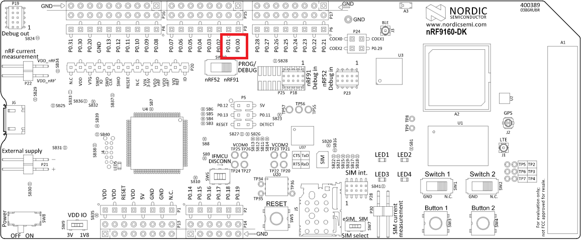
    As mentioned earlier, the GPIO P0.01 and P0.00 will by default not be connected to P0.00 and P0.01 you see on the DK. They are connected to the Interface MCU. So you won't get any input on the oscilloscope. Turn the DK upside down, or see the below picture:

    If you want an alternative routing you will need to update the board controller firmware of the nRF52840 SoC on the nRF9160 DK. In order to do so, you will need to build hello_world and add the code below to the project's device tree. Build for  nrf9160dk_nrf52840 and remember to set the PROG/DEBUG switch on the DK to nRF52.

    &vcom2_pins_routing {
            status = "disabled";
    };

    Documentation:

    https://developer.nordicsemi.com/nRF_Connect_SDK/doc/2.0.0/nrf/ug_nrf9160.html#board-controller 

    https://developer.nordicsemi.com/nRF_Connect_SDK/doc/2.0.0/zephyr/boards/arm/nrf9160dk_nrf52840/doc/index.html#board-controller-firmware

    Best regards,

    Simon


  • Hi Simon,

    I was probing those pins you marked on the DK, however I just tested on my custom board which has a pinout attached directly to pin P0.01.

    When I run the at_client sample with the overlay file, I see UART TX on P0.01 and UART RX on P0.00.

    When I run the aws_iot sample with the overlay file, I don't see any activity on P0.01 and P0.00.

    Is there a reason I would see UART running the at_client sample and not the aws_iot sample while using the overlay file?

    Also, it seems like you were able to run your sample without adding those lines in the prj.conf file to enable SPM. Are we both running the same version of the SDK?

    Thanks,

    Alvin

  • Try to narrow down the issue

    One difference between aws_iot and at_client is that mcuboot is enabled. Try to disable that in aws_iot (CONFIG_BOOTLOADER_MCUBOOT=n) and see if that affects it somehow.

    Since you are able to see activity on P0.01 and P0.00 in hello world, could you try to remove part by part (except for printk, which should output on P0.00 and P0.01) from the aws_iot sample. Eventually you will end up with a clean main.c with only a main() function running printk. Using this approach you can figure out exactly what is causing the issue. If you still don't see anything with a clean main.c, try to remove configs from the prj.conf file. Remember to test regularly so you can pinpoint what is causing the issue..

    Best regards,

    Simon

  • With an empty main.c with just a printk():
    void main(void)
    {
        printk("The AWS IoT sample started, version: %s\n", CONFIG_APP_VERSION);
    }
     
    There is no UART output until I comment out the following lines in prj.conf:
     
    # MCUBOOT
    CONFIG_BOOTLOADER_MCUBOOT=y
    CONFIG_MCUBOOT_IMG_MANAGER=y

    # Image manager
    CONFIG_IMG_MANAGER=y
    CONFIG_FLASH=y
    CONFIG_IMG_ERASE_PROGRESSIVELY=y
    So it looks like it has to do with the MCUboot.
    I was able to get it to launch with the original contents of aws_iot main.c by going into the board file for nrf9160dk_nrf9160_ns (zephyr/boards/arm/nrf9160dk_nrf9160) and editing the nrf9160dk_nrf9160_common-pinctrl.dtsi file. I swapped the pin assignments for UART0 and UART1.
     
    uart1_default: uart1_default {
    group1 {
    psels = <NRF_PSEL(UART_TX, 0, 29)>,
    <NRF_PSEL(UART_RTS, 0, 27)>;
    };
    group2 {
    psels = <NRF_PSEL(UART_RX, 0, 28)>,
    <NRF_PSEL(UART_CTS, 0, 26)>;
    bias-pull-up;
    };
    };

    uart1_sleep: uart1_sleep {
    group1 {
    psels = <NRF_PSEL(UART_TX, 0, 29)>,
    <NRF_PSEL(UART_RX, 0, 28)>,
    <NRF_PSEL(UART_RTS, 0, 27)>,
    <NRF_PSEL(UART_CTS, 0, 26)>;
    low-power-enable;
    };
    };

    uart0_default: uart0_default {
    group1 {
    psels = <NRF_PSEL(UART_TX, 0, 1)>,
    <NRF_PSEL(UART_RTS, 0, 14)>;
    };
    group2 {
    psels = <NRF_PSEL(UART_RX, 0, 0)>,
    <NRF_PSEL(UART_CTS, 0, 15)>;
    bias-pull-up;
    };
    };

    uart0_sleep: uart0_sleep {
    group1 {
    psels = <NRF_PSEL(UART_TX, 0, 1)>,
    <NRF_PSEL(UART_RX, 0, 0)>,
    <NRF_PSEL(UART_RTS, 0, 14)>,
    <NRF_PSEL(UART_CTS, 0, 15)>;
    low-power-enable;
    };
    };
    You mentioned above that the overlay file added doesn't affect MCUboot. Is there an overlay file I can add to the project to assign the pins for MCUboot without editing the board file directly?
  • alvin.le said:
    You mentioned above that the overlay file added doesn't affect MCUboot. Is there an overlay file I can add to the project to assign the pins for MCUboot without editing the board file directly?

    You can do this using the following approach: my_app/child_image/mcuboot/boards/nrf9160dk_nrf9160.overlay (The mcuboot is built as secure, so don't use the 91 ns board selection).

    For more information see Multi-image builds → Image-specific variables

Related