nRF5340 Antenna matching

Hello!

I'm developing my own board featuring the nRF5340.

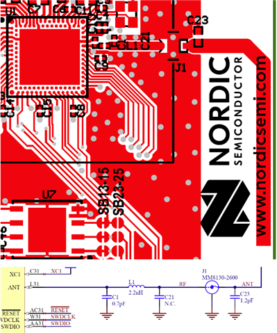
I wanted to add a PCB antenna to my layout and I figured the fastest way to create a functional prototype is to copy the nRF5340 DK antenna.

So I just wanted to have some confirmations before going all in:

  • Is the matching circuit chip side ok? Do I need to consider any other PCB specifications?
  • Is it ok if the RF trace is different from the DK, but matches the 50 ohm anyway?
  • I wanted to place a 0 Ohm Resistor instead of the J1 antenna connector. Is it a problem? This way I can have different trace constraints for the RF trace and the ANTENNA trace
  • If in the future we realize that the antenna doesn't work (either with the DK design or with a custom design), is it possible to have the board revised directly form the Nordicsemi team?

All the best,

Dario

Parents
  • Hi Dario,


    Is the matching circuit chip side ok? Do I need to consider any other PCB specifications?

    - Yes, if you use the QKAA aQFN94. For the CLAA WLCSP the matching network looks different. The antenna needs one component, but also add some extra length on the antenna, for tuning. 

    Is it ok if the RF trace is different from the DK, but matches the 50 ohm anyway?

    - Yes, the trace should be a 50 Ohm transmission line, a coplanar waveguide, so this width should be adjusted for each design.

    I wanted to place a 0 Ohm Resistor instead of the J1 antenna connector. Is it a problem? This way I can have different trace constraints for the RF trace and the ANTENNA trace

    No problem, the J1 on the DK is added to easily do conducted measurements on the radio and enable an external antenna. This is not needed on an end product design, if you are not planning to use an external antenna. 

    If in the future we realize that the antenna doesn't work (either with the DK design or with a custom design), is it possible to have the board revised directly form the Nordicsemi team?

    - You can always submit you HW files, schematic and layout , for HW review. We also help with tuning the antenna and the matching components for the radio.

    Best regards,
    Kaja

Reply
  • Hi Dario,


    Is the matching circuit chip side ok? Do I need to consider any other PCB specifications?

    - Yes, if you use the QKAA aQFN94. For the CLAA WLCSP the matching network looks different. The antenna needs one component, but also add some extra length on the antenna, for tuning. 

    Is it ok if the RF trace is different from the DK, but matches the 50 ohm anyway?

    - Yes, the trace should be a 50 Ohm transmission line, a coplanar waveguide, so this width should be adjusted for each design.

    I wanted to place a 0 Ohm Resistor instead of the J1 antenna connector. Is it a problem? This way I can have different trace constraints for the RF trace and the ANTENNA trace

    No problem, the J1 on the DK is added to easily do conducted measurements on the radio and enable an external antenna. This is not needed on an end product design, if you are not planning to use an external antenna. 

    If in the future we realize that the antenna doesn't work (either with the DK design or with a custom design), is it possible to have the board revised directly form the Nordicsemi team?

    - You can always submit you HW files, schematic and layout , for HW review. We also help with tuning the antenna and the matching components for the radio.

    Best regards,
    Kaja

Children
No Data
Related