BLE doesn't work in the custom board of NRF52840

Hi, 

I recently started using Nordic microcontrollers and I have designed a custom board based on nRF52840 and its works except for Bluetooth.

First of all, I'm using vscode+zephyr to program the board, and the firmware I'm using is a sample firmware "peripheral_uart".

  1. First I tried to upload the firmware on nrf52840DK and it works properly! - I see the device via the nRF connect smartphone app 
  2. Next, I upload  the firmware onto the custom board and...
    1. The firmware is uploaded correctly.
    2. UART connection(TX[P0.14]-RX[P0.09]) OK!
    3. All other gpios are working
    4. Log print "Bluetooth initialized" - but if I try to search for the device with the nRF connect smartphone app, I can't find it

I have done several tests, both hardware(HF crystal is correctly mounted), and software. I've tried resoldering the board but nothing still doesn't work. I have been using these microcontrollers for a short time, so my little experience does not help me solve the problem.

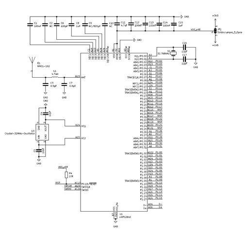
Schematic:
Parents Reply Children
  • salvatore_ said:
    1. The pi network is in the updated wiring diagram and I don't think that is the problem.

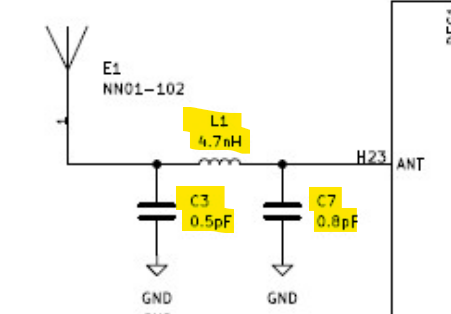
    Are you referring to C3, L1 and C7?

    These are the radio matching/filtering circuit, they can't be used to match the antenna impedance as well.

    salvatore_ said:

    This crystal have a rated CL of 12pF. The correct value for C4 and C5 can be calculated using(assuming insignificant trace capacitance):
    C= 2*CL - 2*Cpin

    The typical pin capacitance(Cpin) for XC1 and XC2 is 3pF. Using this equation a better suited capacitance for C4 and C5 is 18pF.

  • I changed C4 and C5, but the problem is still there. I'm powering and programming the board with nrf52840DK, so I don't think that is the problem. I think the problem is caused by some configuration.

  • If it helps here are the configuration files of the board:

    .dts 

    // Copyright (c) 2022 Nordic Semiconductor ASA
    // SPDX-License-Identifier: Apache-2.0
    
    /dts-v1/;
    #include <nordic/nrf52840_qiaa.dtsi>
    
    / {
    	model = "custom_nRF52840";
    	compatible = "custom,custom-nrf52840";
    
    	chosen {
    		zephyr,sram = &sram0;
    		zephyr,flash = &flash0;
    		zephyr,code-partition = &slot0_partition;
    		zephyr,console = &uart0;
    		zephyr,shell-uart = &uart0;
    
    		zephyr,uart-mcumgr = &uart0;
    		zephyr,bt-mon-uart = &uart0;
    		zephyr,bt-c2h-uart = &uart0;
    	};
    
    	leds {
    		compatible = "gpio-leds";
    		led0: led_0 {
    			gpios = <&gpio0 13 GPIO_ACTIVE_HIGH>;
    			label = "Green LED 0";
    		};
    		led1: led_1 {
    			gpios = <&gpio0 12 GPIO_ACTIVE_HIGH>;
    			label = "Green LED 1";
    		};
    		led2: led_2 {
    			gpios = <&gpio0 15 GPIO_ACTIVE_HIGH>;
    			label = "Green LED 2";
    		};
    		led3: led_3 {
    			gpios = <&gpio0 16 GPIO_ACTIVE_HIGH>;
    			label = "Green LED 3";
    		};
    	};
    
    	aliases {
    		led0 = &led0;
    		led1 = &led1;
    		led2 = &led2;
    		led3 = &led3;
    	};
    };
    
    &adc {
    	status = "okay";
    };
    
    &gpiote {
    	status = "okay";
    };
    
    &gpio0 {
    	status = "okay";
    };
    
    &gpio1 {
    	status = "okay";
    };
    
    &uart0 {
    	compatible = "nordic,nrf-uarte";
    	status = "okay";
    	current-speed = <115200>;
    	tx-pin = <14>; //14//6
    	rx-pin = <9>; //8
    	rts-pin = <0xFFFFFFFF>;
    	cts-pin = <0xFFFFFFFF>;
    };
    
    &flash0 {
    	partitions {
    		compatible = "fixed-partitions";
    		#address-cells = <1>;
    		#size-cells = <1>;
    
    		boot_partition: partition@0 {
    			label = "mcuboot";
    			reg = <0x0 0xc000>;
    		};
    		slot0_partition: partition@c000 {
    			label = "image-0";
    			reg = <0xc000 0x72000>;
    		};
    		slot1_partition: partition@7e000 {
    			label = "image-1";
    			reg = <0x7e000 0x72000>;
    		};
    		scratch_partition: partition@f0000 {
    			label = "image-scratch";
    			reg = <0xf0000 0xa000>;
    		};
    		storage_partition: partition@fa000 {
    			label = "storage";
    			reg = <0xfa000 0x6000>;
    		};
    	};
    };

    _defconfig

    # Copyright (c) 2022 Nordic Semiconductor ASA
    # SPDX-License-Identifier: Apache-2.0
    
    CONFIG_SOC_SERIES_NRF52X=y
    CONFIG_SOC_NRF52840_QIAA=y
    CONFIG_BOARD_CUSTOM_NRF52840=y
    
    # Enable MPU
    CONFIG_ARM_MPU=y
    
    # Enable hardware stack protection
    CONFIG_HW_STACK_PROTECTION=y
    
    # Enable RTT
    CONFIG_USE_SEGGER_RTT=y
    
    # Enable gpio
    CONFIG_GPIO=y
    
    # Enable uart drive
    CONFIG_SERIAL=y
    
    # Enable console
    CONFIG_CONSOLE=y
    CONFIG_UART_CONSOLE=y
    
    # additional board options
    CONFIG_GPIO_AS_PINRESET=y
    
    # CONFIG_PINCTRL=y

  • Since the firmware works correctly on the nRF52840 DK the problem would be with the custom hardware. As I mentioned, if the antenna is not tuned correctly the very little power will be transmitted. If C3, L1 and C7 are the only components between the ANT pin and the antenna, I expect the antenna impedance will not be tune to 50 ohm as is required for good antenna performance.

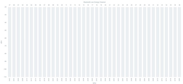
  • I am not very convinced that the problem is the antenna, okay the signal might be very weak but not nonexistent. I also tried to run a test via RSSI Viewer but nothing, it is as if the antenna is not totally connected.

    Could there be some error in the circuit? I followed configuration no. 6.

    https://infocenter.nordicsemi.com/index.jsp?topic=%2Fps_nrf52840%2Fref_circuitry.html

    I cannot find the problem, perhaps I should redesign the board using an antenna PCB as in the dk. However, before redesigning the board I would like to be sure that the problem is that.

Related