nRF52840 matching network for pin 31(ANT), matching circuit needed for regulatory requirements, EMC

Hi,

We are close to going into a certification process but before we start we need to be sure we are not missing out on your recommendations with regards to EMC performance.


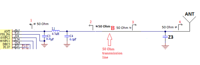
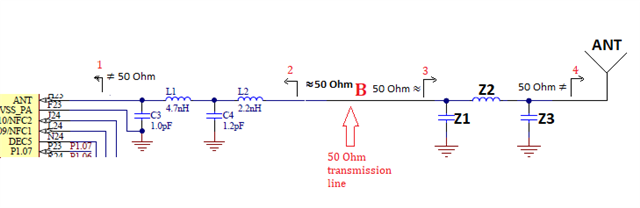
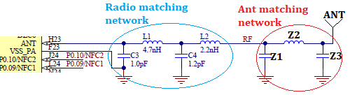
Is the radio matcing network needed for other purposes than matching towards 50ohm? Is it needed for regulatory approval? 


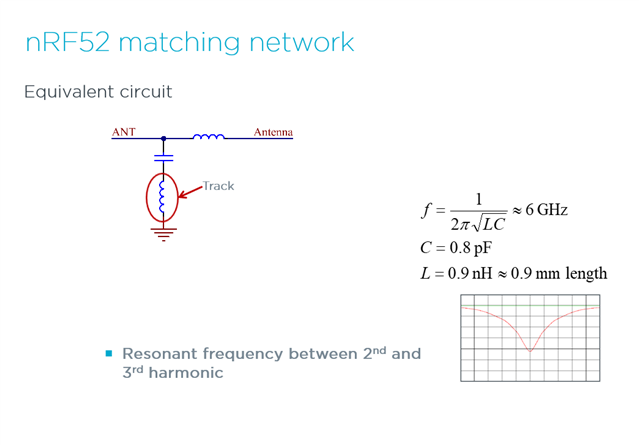
Can you share the impedance at pin 31 (ant port) of the nRF52840?


Thanks,

Regards

Bjørn

  • Hi Bjørn,

    yes a matching network for the radio is needed to be able to pass certification. 

    The point of the matching network is to filter the harmonics and to optimize the output power. 


    The impedance measuring directly on the ANT pin is not possible to do, as you will load the radio with a 50 Ohm load, and this is not the load you want on the radio. 
    The impedance will also change depending on the radio setting. 

    I will add the impedance measurements of the matching network, as this the load the radio sees when it has the correct load.

    Four components matching network: 5127.nRF52833 QIAA matching network.pdf

    Three components matching network: 0830.nRf52840 QIAA matching network (1).pdf

    Both matching network are valid for nRF52840 QIAA, but if you plan to use 8 dBm as TX power I will recommend the matching network with four components as this filters the harmonics best. 


    Have you gotten a HW review from us? If not, upload the HW files to the case, and I can have a look.

    Best regards,
    Kaja

  • Hi, 

    Thank you for the answer and clarifications.

    I did a simple test with a simple circuit and VNA. I made two circuits - both equal to your two alternative matching circuits. I will only give feedback on the 3 component pi network.

    When assuming 50ohm looking back into the nRF52840 through the matching network (as you listed in the post) - we can do the measurement from the other side of the matching network to get an idea about the optimum load for the radio and ANT port. This impedance is  the optimum load impedance. 

    I then simulated this by making a source with this impedance in serie with the matching circuit and observed optimum transfer of power (low S11) through the matching circuit to the 50ohm matched antenna. 

    Anyways, good feedback on the need for this network for regulatory certification and that the ANT impedance is not 50 ohm.

    Thanks

    Regards

  • And note that we tune the matching network for the radio, not with the impedance but by adjusting the components values to optimize the output power and get low enough harmonics. So when tuning the radio we connect it a signal analyzer. 

    Best regards,
    Kaja

  • Hi,

    Can you please specify what spectral components you improved by introducing the matching network? 

    It would be very beneficial to have both the frequencies and the power levels of these components.

    Thanks,

    Regards

    Bjørn 

  • Hi Bjørn,

    here is a description of the two first components in the matching network and the track grounding the parallel capacitor. 


    You can also have a look at our RF performance test guide.


    Best regards,
    Kaja

Related