I am diagnosing pin malfunction in a custom board where I have working code from another version of the board which no longer works.
I am developing against NCS w/ VSCode and extensions.
I am moving from one custom board to another, where the old board used a BT840 pre-made nRF52840 module (the nRF52840, plus caps, crystals, etc) to a board where I place the nRF52840 chip myself along with caps, crystals, etc. My newest custom board was fabricated by JLCPCB within their tolerances.
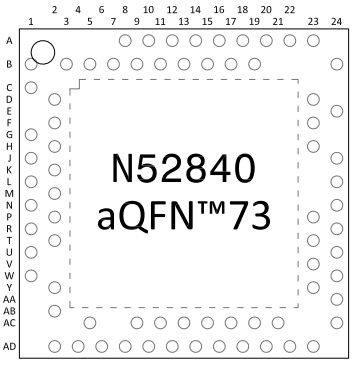
The nRF52840 is the QIAA / aQFN73 version.
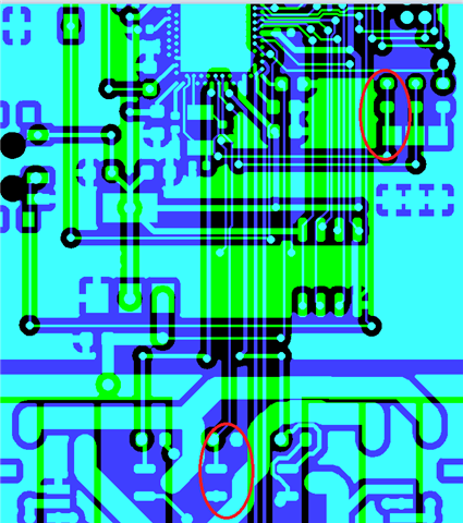
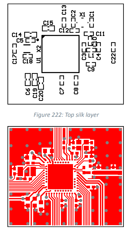
The inner ring of pins, where used, I drop to the bottom layer with a via, and route from there.
My problem is that some, not all, of the pins that are in the inner ring don't appear to be working. This may well be coincidence that they're in the inner ring.
When I say they don't work, I mean bringing the pin high/low in software does not electrically influence the voltage on the trace.
As noted, I have working software from a prior version of this board, where instead of a direct aQFN I used a pre-made module.
So my thinking is there is either some differences between the module behavior and mine, or a physical manufacturing problem. I for sure know there are some differences I have to account for in software, such as this part appears to be a newer nRF52840 and requires changes in accordance with more recent APPROTECT behavior (link) and (link), as well as DC/DC changes (link) so I'm open to the idea there is more I have to account for.
I have unsoldered the chip on one board and confirmed end-to-end continuity from the pin pad to the endpoint of the trace. I have reached out to JLCPCB to see if they believe the board is out of spec or otherwise susceptible to failure and am awaiting reply.
My question to Nordic is, is there something I might be missing moving to a DIY module? How can I investigate?
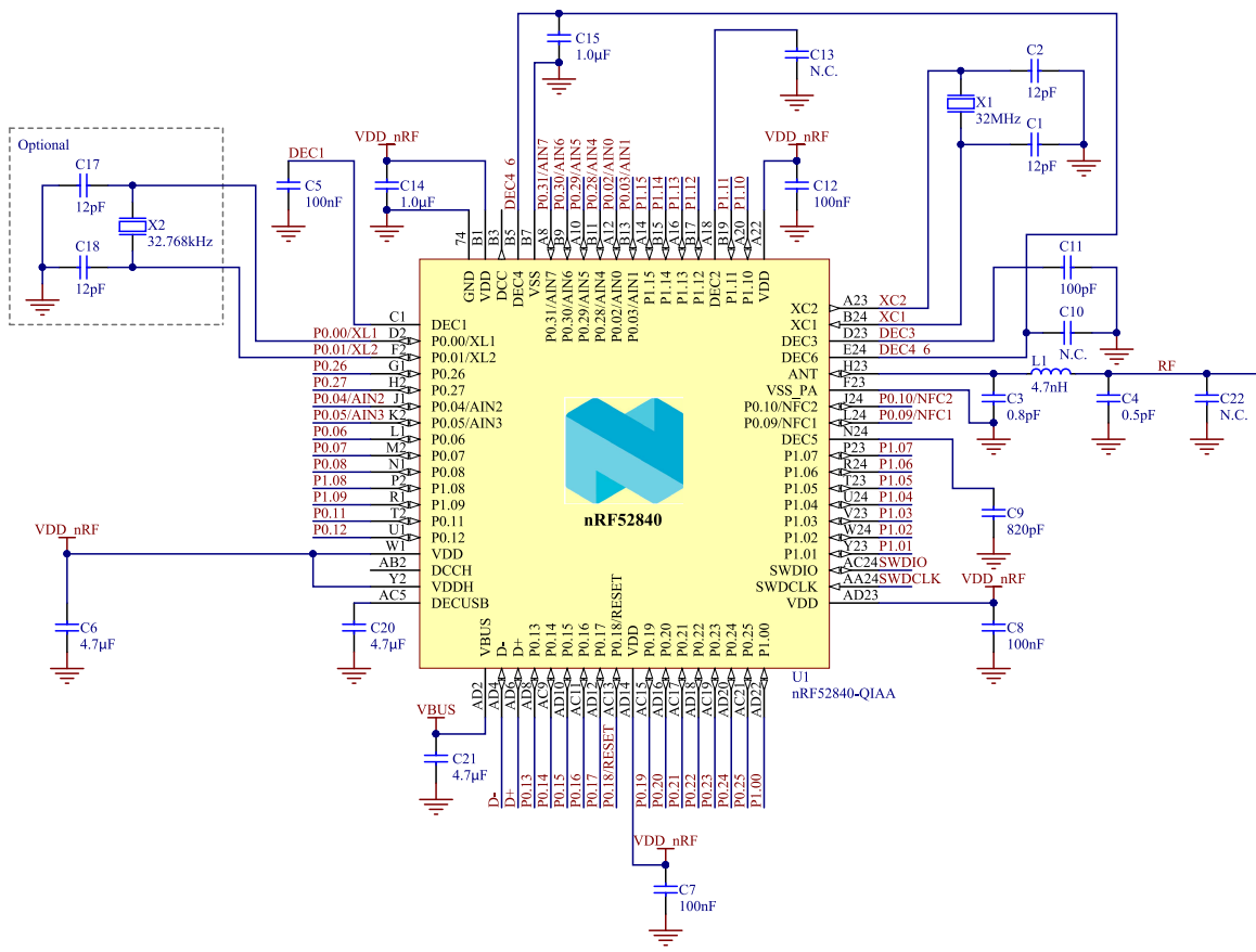
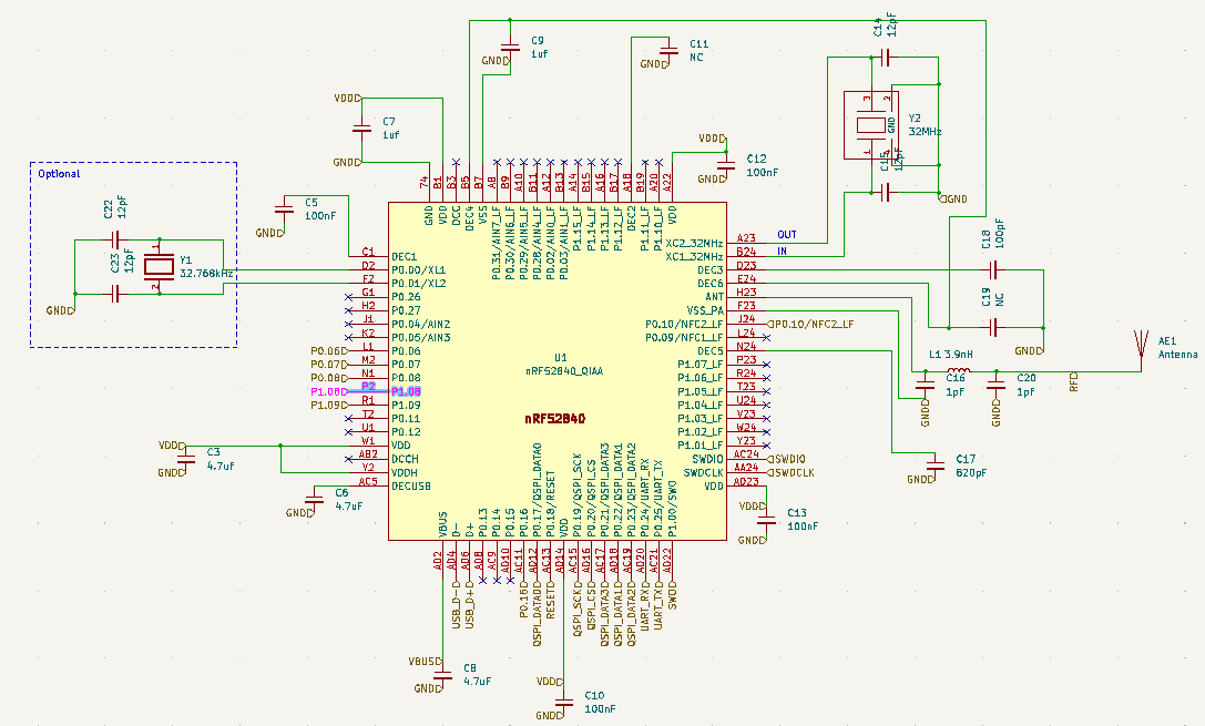
I have followed the Nordic reference circuitry exactly, specifically the (link) specification's 7.3.3 reference layout. First image from the Nordic pdf reference, second from KiCad schematic editor.
I have also followed the footprint layout suggested on p. 609
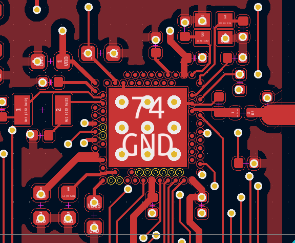
The specific pins which appear to be not working are:
- M2 / 0.07
- P2 / 0.23
- AC19 / 0.25
- AC21 / 1.08
It may well be possible other power-related pins aren't working and I simply don't know.
Please help me work through diagnosing this.
Thanks.
Doug