Unable to program a blank nrf52840

What I'm working on:

I'm working on a small project using this nrf52840 module:

www.minew.com/.../

Access to source:

If it helps to understand my issue, all the design files including output gerbers are available here:

github.com/.../e1b075a91563f4ed9a8b609f1a4538d70e4fa849

I basically copied the 52840 Dongle as close as I could.

My problem:

I'm trying to do my first "hello world" communication to the chip on the SWD bus through a:

pyocd client -> CMSIS-DAP firmware -> MAX32625PICO -> nRF52840.

I get this error:

Exception while initing board: No ACK received

Log:

$ pyocd commander -c reset -vvvvv
0000664 D Project directory: /home/fgervais/personal/project-nrf-princess-dress/application [session]
0000668 D Loading config from: /home/fgervais/personal/project-nrf-princess-dress/application/pyocd.yaml [session]
0000675 D Project directory: /home/fgervais/personal/project-nrf-princess-dress/application [session]
0000675 D Loading config from: /home/fgervais/personal/project-nrf-princess-dress/application/pyocd.yaml [session]
0000700 D CMSIS-DAP v2 probe 0000008078b1036600000000000000000000000097969906: firmware version 0257, protocol version 2.1.0 [dap_access_cmsis_dap]
0000706 I Target type is nrf52840 [board]
0000728 D Running task load_svd [sequencer]
0000728 D Running task pre_connect [sequencer]
0000728 D Running task dp_init [sequencer]
0000728 D Running task lock_probe [sequencer]
0000728 D Running task get_probe_capabilities [sequencer]
0000728 D Running task connect [sequencer]
0000735 D Default wire protocol selected; using SWD [dap]
Exception while initing board: No ACK received

What I did so far:

- I'm applying 5v to the VDDH, I get 1.8v out at the VDD.
- The P0.18 pin is pulled high but I don't think it matters on a blank chip.
- I see SWDIO pulled high and SWDCLK pulled low when idle.
- When communicating, the SWD signals look good but I also try lowering the clock speed from 1MHz to 100KHz to see if that would help. It doesn't.

My question:

- Any idea what I could try next?

Parents
  • Hi,

    We do not support programming through OpenOCD.

    You should get a J-Link debugger (or a nRF5x DK), to check if you are able to program your module correctly. 

    I will leave the thread open in case someone in the community knows what causes the issue you are seeing and can help you out.

    Best regards,
    Jørgen

  • Do you mean if the DK can program a target running at 1.8V supply voltage?

    It should be possible if you get a nRF52840 DK. With the default configuration and wiring (powered through the J2 interface MCU USB port), the DK will be power by 3.0V from a regulator on the board. If you power the board through the nRF_USB (J3), and set the nRF Power Source switch (SW9) to USB, the board will be powered by the voltage controlled by REGOUT0. If this register is set to 1.8V, the debug chip on the DK will also run at 1.8V, and SWD pins will use this voltage, and allow programming of external boards running off other voltage levels. See Power supply for more details about the power supply modes on the DK.

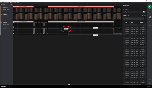
    This is a logic trace of the SWD pins on P20 with above configuration/wiring:

    Best regards,
    Jørgen

Reply
  • Do you mean if the DK can program a target running at 1.8V supply voltage?

    It should be possible if you get a nRF52840 DK. With the default configuration and wiring (powered through the J2 interface MCU USB port), the DK will be power by 3.0V from a regulator on the board. If you power the board through the nRF_USB (J3), and set the nRF Power Source switch (SW9) to USB, the board will be powered by the voltage controlled by REGOUT0. If this register is set to 1.8V, the debug chip on the DK will also run at 1.8V, and SWD pins will use this voltage, and allow programming of external boards running off other voltage levels. See Power supply for more details about the power supply modes on the DK.

    This is a logic trace of the SWD pins on P20 with above configuration/wiring:

    Best regards,
    Jørgen

Children
Related