Low Power Blinky Example - Power Consumption Problem - Power Profiler Kit II and nRF52840 DK

Hello,

I have tried running Blinky example with some Low Power directives in the code without success. I came here for help then.

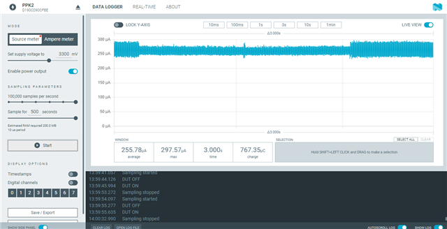
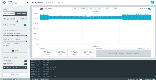
The current consumption used by the example, based on the Blinky sample, on the nRF52840 DK, stays around 2mA when the LED is off.

I am using NCS v2.1.0 and nRF52840 DK. I have used the Voltage Source meter mode for consumption measurement on the PPK II. 

Here is the code:

4276.blinky.rar

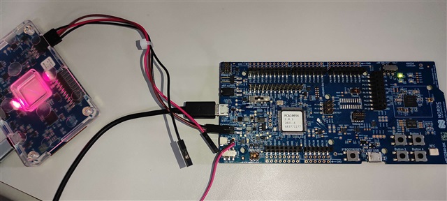
Though the USB cable is connected to the DK in the image below, it is disconnected from the PC USB.
Parents Reply Children
  • Hi thiago_hd,

    Sorry for the long wait.

    I think what you perceive to be not working is that you find 2mA is way too much when the LED is off?

    As you are not powering the board with the USB cable, the PPK is powering the entire board. Therefore, the 2mA you see is the total consumption of the board, not just the nRF chip.

    If you put the USB cable in, you will see only the current drawn by the nRF DUT. Then you can see that the device running your source code is drawing very little current. Only about 15.74 uA.

    Sorry again for the long wait.

    Best regards,

    Hieu

  • Hello  

    Could you explain for me in a drawing how am I supposed to connect PPK to the nRF USB connector in the nRF52840DK?

    I am not sure how I connect PPK this way.

  • Hi thiago_hd,

    I think you have misunderstood me. I am talking about the same USB port on the DK's short edge as the one you are using.

    Your setup as in the picture is already fine, just connect the USB cable to a power source/PC. 

    Best regards,

    Hieu

  •  it doesnt make any sense to me to plug two power sources (USB and PPK) at the same time. Let me tell you what is the setup that I have.

    I plugged PPK's Vout and GND pins in the P21 External Supply connector + and - pins, respectively.

    I have the USB plugged (and powered, since you requested it) on J2 USB Connector (the same port we use for debugging/flashing).

    P22 (nRF current measurement) is short circuited

    SW8 (Power) switch is ON.

    SW10 (Vext -> nRF) is OFF.

    SW9 (nRF Power Source) is set to VDD (instead of Li-Po and USB).

    SW6 (nRF ONLY | DEFAULT) is set to DEFAULT.

    SW7 (TRACE) is set to Default.

    This is what is happening now:

Related