Low Power Blinky Example - Power Consumption Problem - Power Profiler Kit II and nRF52840 DK

Hello,

I have tried running Blinky example with some Low Power directives in the code without success. I came here for help then.

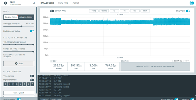
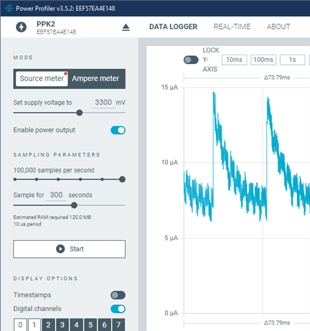
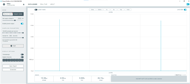
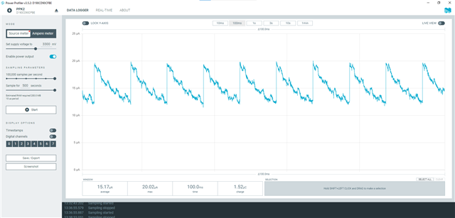
The current consumption used by the example, based on the Blinky sample, on the nRF52840 DK, stays around 2mA when the LED is off.

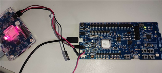
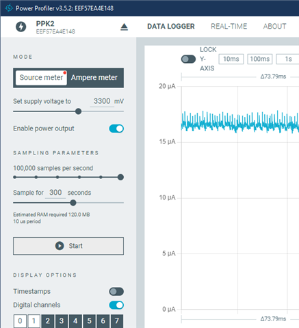
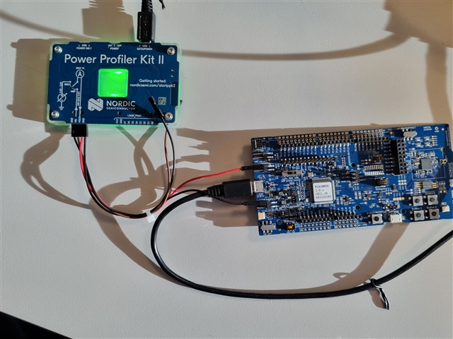
I am using NCS v2.1.0 and nRF52840 DK. I have used the Voltage Source meter mode for consumption measurement on the PPK II. 

Here is the code:

4276.blinky.rar

Though the USB cable is connected to the DK in the image below, it is disconnected from the PC USB.

Parents Reply Children
  •  it doesnt make any sense to me to plug two power sources (USB and PPK) at the same time. Let me tell you what is the setup that I have.

    I plugged PPK's Vout and GND pins in the P21 External Supply connector + and - pins, respectively.

    I have the USB plugged (and powered, since you requested it) on J2 USB Connector (the same port we use for debugging/flashing).

    P22 (nRF current measurement) is short circuited

    SW8 (Power) switch is ON.

    SW10 (Vext -> nRF) is OFF.

    SW9 (nRF Power Source) is set to VDD (instead of Li-Po and USB).

    SW6 (nRF ONLY | DEFAULT) is set to DEFAULT.

    SW7 (TRACE) is set to Default.

    This is what is happening now:

  • Hi  ,

    thiago_hd said:
    it doesnt make any sense to me to plug two power sources (USB and PPK) at the same time.

    Yes, I agree that it does not make much immediate sense why the measurement is only valid when you plug in the debugger cable.
    I tried to dive into the schematic to show you how it would work, but was not very successful due to my limited HW expertise. If you wish to fully understand the details, please let me know and I will try to pull in more knowledgeable people.

    But in any case, the J2 USB Connector has to be plugged in. I found an official source here: https://infocenter.nordicsemi.com/topic/ug_ppk2/UG/ppk/measure_current_source_meter.html
    The picture is small, but you can open it on a separate tab and zoom in to read the details.
    The source also points out one thing both you and I did wrong. PPK2-VOUT has to connect to nRF52840 DK P22 pin VDD_nRF (the pin would be the upper one in your picture.

    thiago_hd said:

    This is what is happening now:

    Unfortunately, I cannot reproduce this. Are you opening any VCOM maybe? What is your USB cable plugging into?


    Below is what I see in my setup yesterday and today:

    Yesterday setup, same as your original one, with J2 plugged in:

    Today setup, as instructed by the guide linked above

    Finally, here is my setup today

    USB plugged on J2 USB Connector

    P22-VDD_nRF (see picture) connected to PPK2-VOUT

    P21-Ground connected to PPK2-Ground

    SW8 (Power) switch is ON.

    SW10 (Vext -> nRF) is OFF.

    SW9 (nRF Power Source) is set to VDD (instead of Li-Po and USB).

    SW6 (nRF ONLY | DEFAULT) is set to DEFAULT.

    SW7 (TRACE) is set to Default.

  • Hello  I got to reproduce your results.

    However, there is one thing I had to do.

    I had to open the SB40 short circuit (R90).

    Then I got this result:

    Can you explain to me why I can only see the turn ON/OFF event of the LED, instead of it's current consumption during the time that the LED is ON? Is it because the current draw for the LED is coming from the USB port? Is there a way to change this so the LED will be fed by the PPK2?

    How can I reduce the current consumption even more? I wanted to achieve as little as 5 uA on average, during the time where everything is SUSPENDED.

Related