Hello all!!!
I am new to the field of antennas and have lately been struggling in understanding antenna matching networks. All that I know as of now is that antenna matching networks are necessary only when there is a mismatch between source and load impedances (output and input respectively). My doubts are as follows:
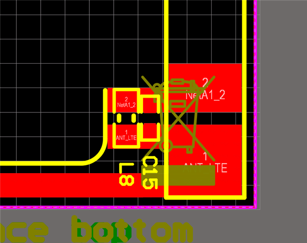
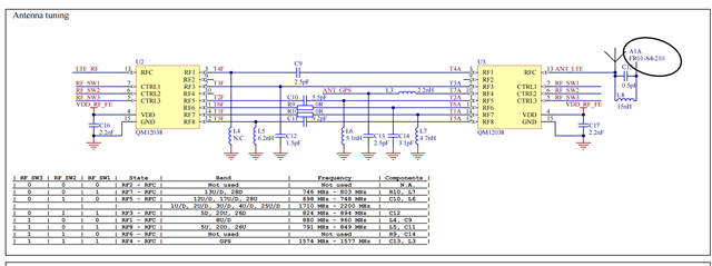
1. What does the N.C. stand for below inductor L5 and capacitor C85? (in the image below)
2. What is the second terminal of the capacitor and the inductor connected (refer the highlight in the image below) (P.S.: I am assuming it is connected to ground)
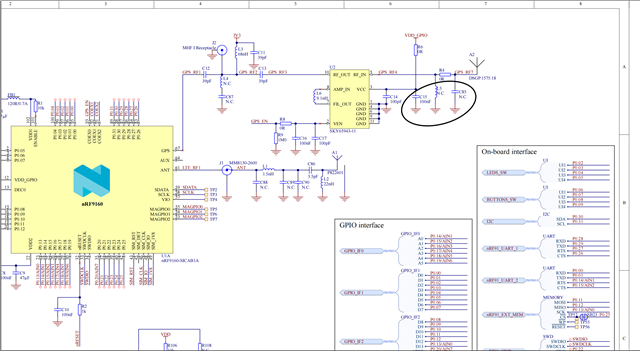
3. In the image below, since the antenna A1A FR01-S4-210 and the switch QM12038 both are matched to 50 ohm impedance, what is the need for the additional circuit connected to the antenna (I am assuming it is a antenna matching circuit :) )?
The help will be sincerely appreciated. Thank you!!!!