I'm profiling the current consumption of our device, on an nRF5340 module, at SDK 2.1.0.
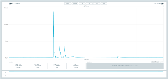
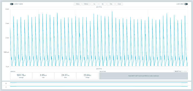
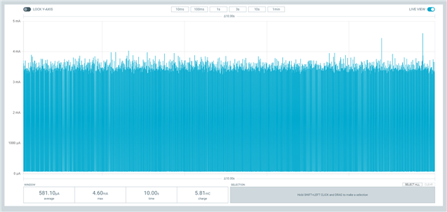
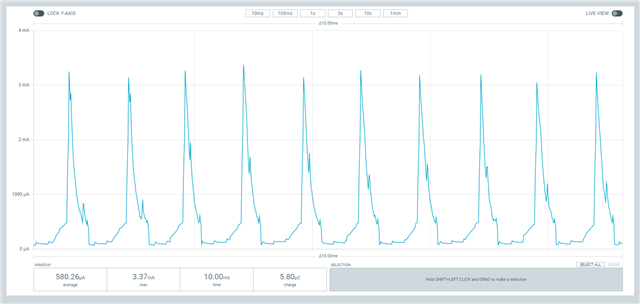
So far as I can tell, the ADC is using approximately 1000 uA. It's sampling via PPI, and is triggered from an external clock signal at 1 kH.
The current consumption figures for the SAADC here show typical current consumption based on different configuration options. It looks like ~1000 uA is on the high end of what is expected, and that setting LPOP=LowPower would save us a considerable amount of current.
However I can't find anything about LPOP or LowPower anywhere else, either in the SAADC documentation or in the SDK.
Any tips as to where This can be enabled? I've seen this for an old version of the SDK, but it seems to come down to setting saadc_config.low_power_mode = true; which isn't part of the config struct in the current SDK.

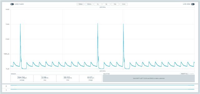
 or sometimes this
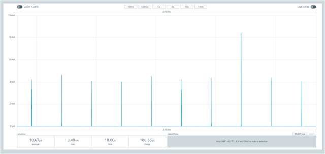