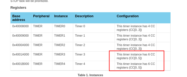
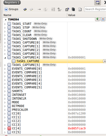
I am facing a problem. Two sensors are triggering with data_ready pins and a timer value is captured upon the event. But the value can be stored only in RAM if a context switch happens. But this depends on the processor usage. Therefore, it can happen that one sensor triggers a capture event, but the interrupt routine is delayed due to softdevice processing etc. and in the meantime the other sensor triggers a more recent capture. In this case the timing is screwed.
I've tried to use another capture channel of the same timer but somehow the NRF_TIMER_TASK_CAPTURE4 of timer4 is permanent at the same value. But I have to admit that I am not sure if the event is correctly configured since the code in the header is always greyed out . And I do not know where TIMER_INTENSET_COMPARE4_Msk is defined.
/** @brief Timer tasks. */
typedef enum
{
    NRF_TIMER_TASK_START    = offsetof(NRF_TIMER_Type, TASKS_START),      ///< Task for starting the timer.
    NRF_TIMER_TASK_STOP     = offsetof(NRF_TIMER_Type, TASKS_STOP),       ///< Task for stopping the timer.
    NRF_TIMER_TASK_COUNT    = offsetof(NRF_TIMER_Type, TASKS_COUNT),      ///< Task for incrementing the timer (in counter mode).
    NRF_TIMER_TASK_CLEAR    = offsetof(NRF_TIMER_Type, TASKS_CLEAR),      ///< Task for resetting the timer value.
    NRF_TIMER_TASK_SHUTDOWN = offsetof(NRF_TIMER_Type, TASKS_SHUTDOWN),   ///< Task for powering off the timer.
    NRF_TIMER_TASK_CAPTURE0 = offsetof(NRF_TIMER_Type, TASKS_CAPTURE[0]), ///< Task for capturing the timer value on channel 0.
    NRF_TIMER_TASK_CAPTURE1 = offsetof(NRF_TIMER_Type, TASKS_CAPTURE[1]), ///< Task for capturing the timer value on channel 1.
    NRF_TIMER_TASK_CAPTURE2 = offsetof(NRF_TIMER_Type, TASKS_CAPTURE[2]), ///< Task for capturing the timer value on channel 2.
    NRF_TIMER_TASK_CAPTURE3 = offsetof(NRF_TIMER_Type, TASKS_CAPTURE[3]), ///< Task for capturing the timer value on channel 3.
#if defined(TIMER_INTENSET_COMPARE4_Msk) || defined(__NRFX_DOXYGEN__)
    NRF_TIMER_TASK_CAPTURE4 = offsetof(NRF_TIMER_Type, TASKS_CAPTURE[4]), ///< Task for capturing the timer value on channel 4.
#endif
#if defined(TIMER_INTENSET_COMPARE5_Msk) || defined(__NRFX_DOXYGEN__)
    NRF_TIMER_TASK_CAPTURE5 = offsetof(NRF_TIMER_Type, TASKS_CAPTURE[5]), ///< Task for capturing the timer value on channel 5.
#endif
} nrf_timer_task_t;