~30uA and ~24uA current peaks in SYSTEM ON with BLE connection

Hello everyone. I am developing a peripheral device capable of connecting to a central device. The device consumes 1.6uA on connection, but there are different current peaks where the highest peaks are 30uA and 20uA every 8 seconds approximately.

Is it normal? is it due to the refresh mode of the DCDC regulator? if there is some way to eliminate this rare (rare for me) peak I woul like to know it.

I am working with:

  1. NRF52832
  2. SDK 16.0
  3. ble_app_template example

regards.
Parents
  • Hi,

    How are you measuring this? I ask because he peak currents you describe seem too low, and also a idle consumption of 1.6uA is a bit too low.

    That said, the Bluetooth examples calibrate the LFRC oscillator clock every 8 seconds, so if that is used, it is expected that you see a peak then (though in reality it would be higher but very short).

    Is it normal? is it due to the refresh mode of the DCDC regulator?

    No, this does not sound like the refresh mode. That will happen more frequently (depending on how you measure you may not be able to properly see the refresh mode peaks).


  • How are you measuring this? I ask because he peak currents you describe seem too low, and also a idle consumption of 1.6uA is a bit too low.

    I am using a simple voltimeter, I don't have oscilloscope or the PPK :( . I made the test in two different multimeters, in the one of them the lowest medition is 1.6 uA, in the other the lowest medition is 2.6 uA. I dont have an accurate graph of the current consumtion.

    the Bluetooth examples calibrate the LFRC oscillator clock every 8 seconds, so if that is used, it is expected that you see a peak then (though in reality it would be higher but very short).

     I made the follow configuration of the LFCLKSRC register:

    #define CLOCK_LFCLKSRC_SRC_Xtal (1UL) /*!< 32.768 kHz crystal oscillator */

    #define CLOCK_LFCLKSRC_SRC_Pos (0UL) /*!< Position of SRC field. */

       NRF_CLOCK->LFCLKSRC =CLOCK_LFCLKSRC_SRC_Xtal<<CLOCK_LFCLKSRC_SRC_Pos;

        NRF_CLOCK->TASKS_LFCLKSTART = 1;

        while(NRF_CLOCK->EVENTS_LFCLKSTARTED == 0);

  • Hi,

    eudaldo said:
    the above, is a normal performant?

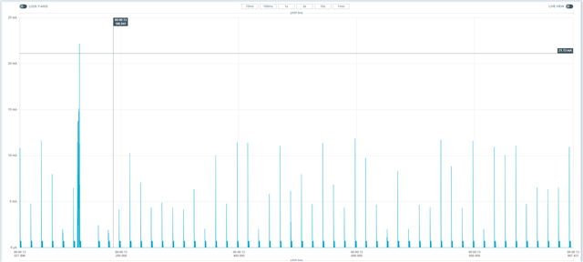
    I do not know what the device is doing, but if it is only Bluetooth, then the peaks are too high. Other than that, the time axis is so cramped that it is not possible to see any recognizable waveform so even if I knew what the device was doing it would not be possible to say much about it from this plot.

    If you only use Bluetooth, then the average current consumption here is too high (you can compare with the online power profiler to get ballpark numbers). That could be related to a measurement issue, as as mentioned the peaks in your plot are suspiciously high. So I would be interested in details about your HW, how you have connected it to the PPK2, and how you have configured it / how you are measuring.

  • I do not know what the device is doing, but if it is only Bluetooth, then the peaks are too high. Other than that, the time axis is so cramped that it is not possible to see any recognizable waveform so even if I knew what the device was doing it would not be possible to say much about it from this plot.

    Yes, I am using only Buetooth LE. This is my main function:

    int main(void)
    {
    
        ret_code_t err_code; 
       
        power_management_init();
    
        ble_stack_init();  
       
        enable_DCDC_regulator(); 
    
        gap_params_init();   
    
        gatt_init();    
          
        advertising_init();  
      
        conn_params_init();
        
        advertising_start();
    
        // Enter main loop.
        for (;;)
        {
            sd_app_evt_wait();
        }
    }

    I attached  the PPK2 file of the measures:

    ppk-20221117T171441-data-logger.zip

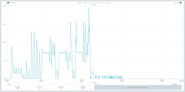
    I attach a better screen shot of the plot.

    If you only use Bluetooth, then the average current consumption here is too high (you can compare with the online power profiler to get ballpark numbers). That could be related to a measurement issue, as as mentioned the peaks in your plot are suspiciously high. So I would be interested in details about your HW, how you have connected it to the PPK2, and how you have configured it / how you are measuring.

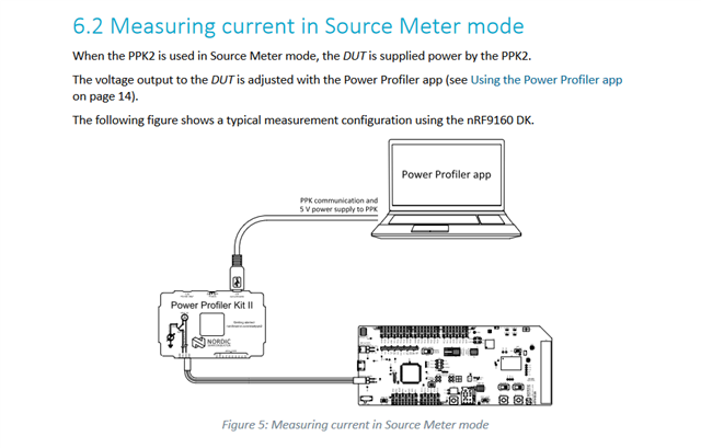
    Yes, I am using the PPK2 in source mode:

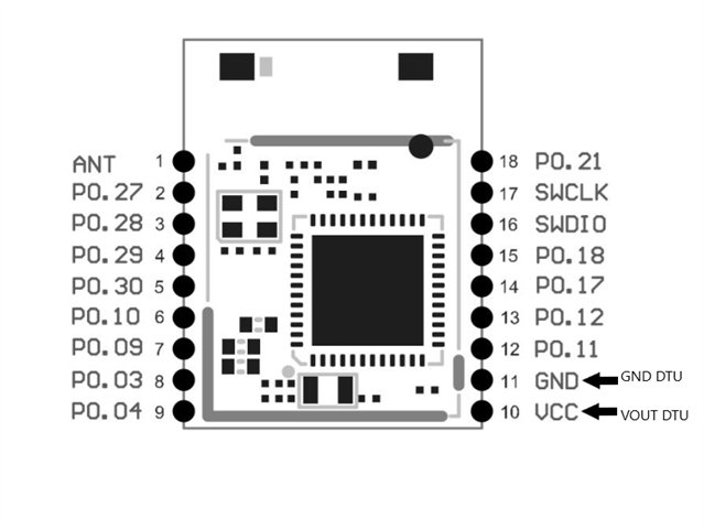
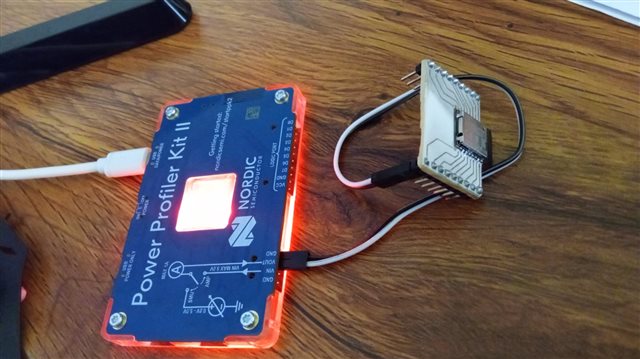
    the connections are the following:

  • Hi,

    I have discussed this case with a colleague of mine, and it seems you are seeing a limitation with the PPK 2. In some cases there can flow a negative current, and that will cause problems with the measurements, which will interpret it as a high (normal/positive) current. For now, this can be worked around in one of two ways:

    1. Use a diode in series to prevent any negative current. Note that you will need to compensate for the voltage drop over the diode in this case. This is probably the simplest workaround.
    2. Use a lot of capacitors on VDD to even out and prevent any negative current. This would reduce the resolution though, as everything gets smoothed out, but you should get decent average numbers.

    Einar

  • Update: We are working on a new release of the Power profiler software that will include firmware for the PPK 2 that fixes this issue. I cannot say exactly when it will be out, though.

    Edit: This is fixed in Power Profiler 3.5.3 that was just released.

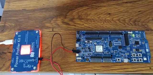
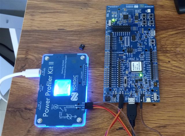
  • I have a NRF52840 PCA10056, and I download the ble_app_blink of the SDK version 17.1.0 and I got the following result in the two modes:

    SOURCE MODE:

    connections:

    results:


    AMPERE MODE:

    connections:

    results:

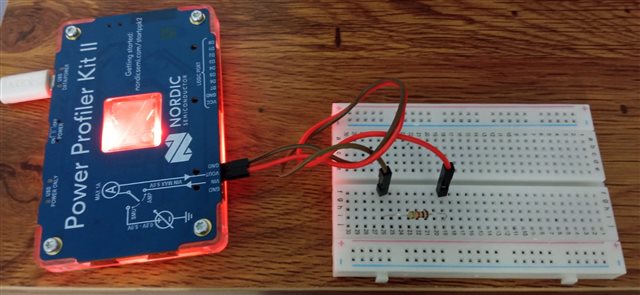
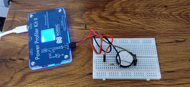
    I test the PPK2 using a simple 1K Ohm resistance and CR2032 ( 2.8 V) battery. and the results of the test in both modes, are the expected, nothing out of the ordinary.

    source mode:

    ampere mode

    What does it happen? What is it wrong?

Reply
  • I have a NRF52840 PCA10056, and I download the ble_app_blink of the SDK version 17.1.0 and I got the following result in the two modes:

    SOURCE MODE:

    connections:

    results:


    AMPERE MODE:

    connections:

    results:

    I test the PPK2 using a simple 1K Ohm resistance and CR2032 ( 2.8 V) battery. and the results of the test in both modes, are the expected, nothing out of the ordinary.

    source mode:

    ampere mode

    What does it happen? What is it wrong?

Children
  • Hi,

    When measuring the DK in source mode you need to ensure that the voltage from the PPK is exactly the same as the VDD on the DK (which should be 2.7 V after the protection diodes). If the voltage differs, there will be a current via the SWD lines and nRESET to the debugger, which will affect the measurements. To avoid this, you should measure the voltage of the PPK output and VDD on the DK, and configure the output voltage of the PPK to the exact same voltage.

    (Also, make sure you update the Power Profiler software to the latest release to fix the issue we have discussed before in this thread).

Related