How does Deep Power-Down Work with QSPI and some example code.

QSPI_Test.ino

Hi,

Just wondered about the following ....

Strange parts of this code ... Or things I don't understand

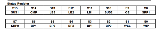
After the first READ in Setup() it successfully reads the data (Returns 0 = NRFX_SUCCESS), but the status flag
has the top 8 bits set to 0xFF which causes nrfx_qspi_mem_busy_check() to show 17 (Returns 17 = NRFX_ERROR_BUSY).
However masking the STATUS register with 8 reveals the Ready Status = 1, QSPI is ready!
This was why I wrote the QSPI_IsReady().

nrf_qspi_phy_conf_t not visible as a structure if you try and set it like this

    QSPIConfig.phy_if {
        .xxx = yyy,
        .aaa = bbb
     };
 
I don't know what the significance of the 48ms Deep Power-down Mode (DPM) is.
Will it go into DPM if not used for 48ms and then take 48ms to wake up if instructed?

Thanks

Paul

Parents
  • Hi Vidor,

    Thanks for replying so quickly.

    The SReg = 0xFF and stays like that until I do a write.  I have pasted the test output from my (slightly modified) program.

    Thanks for the datasheet, I was using the nRF52840_PS_v1.1.pdf, I think they are the same (or at first glance they are).

    The QSPI flash I am using is the one built into the chip itself.

    I can't get it to work with all 4 IO pins as well (Just tried today, it will work with 2 IO pins, reading is faster, writing not so much).

    Paul

    QSPI Test Output

    (Setup) QSPI Initialising ...
    (QSPI_Initialise) Wait for QSPI to be ready ...
    (QSPI_Initialise) QSPI is ready
    (Setup) QSPI initialised and ready
    (Setup (After initialise)) QSPI is busy/idle ... Result = 0
    (Setup (After initialise)) QSPI Status flag = 0xA (from NRF_QSPI) or 0xA (from my QSPI_Status_Ptr Pointer)
    (Setup) QSPI IFCONFIG0 = 0x89
    (Setup) QSPI IFCONFIG1 = 0x89
    (Setup) QSPI Pins
      (Setup) IO0 = 0x14
      (Setup) IO1 = 0x18
      (Setup) IO2 = 0x16
      (Setup) IO3 = 0x17
    (Setup) QSPI is about to be read and then erased. Current busy state is = 0
    (Setup (Before read)) QSPI is busy/idle ... Result = 0
    (Setup (Before read)) QSPI Status flag = 0xA (from NRF_QSPI) or 0xA (from my QSPI_Status_Ptr Pointer)
    (Setup) QSPI took 8ms to read 64Kb ... Read result = 0
    QSPI Data : 0x0 0x1 0x2 0x3 0x4 0x5 0x6 0x7 0x8 0x9
    (QSPI_Erase) Erasing 64Kb of flash memory
    ((QSPI_Erase) Waiting Loop Breakout) QSPI is busy/idle ... Result = 0
    ((QSPI_Erase) Waiting Loop Breakout) QSPI Status flag = 0xFF00000A (from NRF_QSPI) or 0xFF00000A (from my QSPI_Status_Ptr Pointer)
    ((QSPI_Erase) Finished Waiting) QSPI is busy/idle ... Result = 0
    ((QSPI_Erase) Finished Waiting) QSPI Status flag = 0xFF00000A (from NRF_QSPI) or 0xFF00000A (from my QSPI_Status_Ptr Pointer)
    (QSPI_Erase) QSPI took 0ms to erase 64Kb of flash memory
    (Setup (After erase)) QSPI is busy/idle ... Result = 0
    (Setup (After erase)) QSPI Status flag = 0xA (from NRF_QSPI) or 0xA (from my QSPI_Status_Ptr Pointer)
    (Setup) QSPI read after erase
    (Setup) QSPI took 17ms to read 64Kb ... Read result = 0
    (Setup (After read and erase)) QSPI is busy/idle ... Result = 0
    (Setup (After read and erase)) QSPI Status flag = 0xFF00000A (from NRF_QSPI) or 0xFF00000A (from my QSPI_Status_Ptr Pointer)
    QSPI Data : 0xFFFF 0xFFFF 0xFFFF 0xFFFF 0xFFFF 0xFFFF 0xFFFF 0xFFFF 0xFFFF 0xFFFF
    (Setup) Just before QSPI write
    (Setup) QSPI took 352ms to write 64Kb ... Write result = 0
    (Setup (After write)) QSPI is busy/idle ... Result = 0
    (Setup (After write)) QSPI Status flag = 0xA (from NRF_QSPI) or 0xA (from my QSPI_Status_Ptr Pointer)
    (Setup) Just before QSPI read
    (Setup) QSPI took 8ms to read 64Kb ... Read result = 0
    (Setup (After read)) QSPI is busy/idle ... Result = 0
    (Setup (After read)) QSPI Status flag = 0xFF00000A (from NRF_QSPI) or 0xFF00000A (from my QSPI_Status_Ptr Pointer)
    QSPI Data : 0x0 0x2 0x4 0x6 0x8 0xA 0xC 0xE 0x10 0x12

  • Hi Paul,

    There is no QSPI flash in the nRF52840 IC package, so I guess the P25Q16H flash must be placed next the nRF inside the Seeed Studio module.

    Cheets said:
    I can't get it to work with all 4 IO pins as well (Just tried today, it will work with 2 IO pins, reading is faster, writing not so much).

    Where did you find the pin numbers?

    Vidar

Reply Children
Related