Hi there
I'm using Asset tracker v2 as a base for my application with AWS, however I wanted the FOTA to download to external flash, as the Asset tracker application is large, and leaves little room for any other application code.
I'm able to FOTA, to external SPI flash using MCUBoot, however once the download is complete I get an error
<err> dfu_target_mcuboot: boot_request_upgrade for image-0 error -14
Any help appreciated.
Here is the debug
[00:07:17.860,687] <inf> download_client: Downloaded 323584/328496 bytes (98%)
[00:07:18.965,179] <inf> download_client: Downloaded 324608/328496 bytes (98%)
[00:07:20.061,065] <inf> download_client: Downloaded 325632/328496 bytes (99%)
[00:07:21.231,323] <inf> download_client: Downloaded 326656/328496 bytes (99%)
[00:07:22.301,300] <inf> download_client: Downloaded 327680/328496 bytes (99%)
[00:07:23.365,417] <inf> download_client: Downloaded 328496/328496 bytes (100%)
[00:07:23.365,509] <dbg> STREAM_FLASH: stream_flash_erase_page: Erasing page at offset 0x00050000
[00:07:23.494,506] <inf> download_client: Download complete
[00:07:23.497,711] <dbg> STREAM_FLASH: stream_flash_erase_page: Erasing page at offset 0x000e0000
[00:07:23.618,499] <err> dfu_target_mcuboot: boot_request_upgrade for image-0 error -14
[00:07:23.618,530] <err> fota_download: dfu_target_done error: -14
[00:07:23.618,530] <err> aws_fota: FOTA_DOWNLOAD_EVT_ERROR
[00:07:23.618,560] <dbg> aws_fota: update_job_execution: update_job_execution, status: 3, version_number: 1236
[00:07:23.620,544] <err> aws_iot: AWS_FOTA_EVT_ERROR
[00:07:23.620,544] <dbg> aws_iot_integration: aws_iot_event_handler: AWS_IOT_EVT_FOTA_ERROR
[00:07:23.620,574] <dbg> cloud_module: cloud_wrap_event_handler: CLOUD_WRAP_EVT_FOTA_ERROR
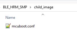
The only files I had to add to the asset_tracker application were.
\child_image\mcuboot\boards\thingy91_nrf9160.overlay
/ {
	chosen {
		nordic,pm-ext-flash = &is25lp032d;
	};

};


&spi3 {
	compatible = "nordic,nrf-spim";
	status = "okay";

    pinctrl-0 = <&spi3_default>;
	pinctrl-1 = <&spi3_sleep>;
	pinctrl-names = "default", "sleep";

	cs-gpios = < &gpio0 7 GPIO_ACTIVE_LOW >,< &gpio0 7 GPIO_ACTIVE_LOW >;
	is25lp032d: is25lp032d@0 {
		compatible = "jedec,spi-nor";
		label = "IS25LP032D";
		reg = < 0 >;
		spi-max-frequency = < 40000000 >;
		wp-gpios = < &gpio0 8 GPIO_ACTIVE_LOW >;
		hold-gpios = < &gpio0 10 GPIO_ACTIVE_LOW >;
		size = < 0x2000000 >;
		has-dpd;
		t-enter-dpd = < 3000 >;
		t-exit-dpd = < 30000 >;
		jedec-id = [ 9d 60 16  ];

	};
};

&uart0 {
	compatible = "nordic,nrf-uarte";
	status = "okay";
	/delete-property/ cts-pull-up;
	//hw-flow-control;
    pinctrl-0 = <&uart0_default_alt>;
	pinctrl-1 = <&uart0_sleep_alt>;
	pinctrl-names = "default", "sleep";


};


&pinctrl {
	uart0_default_alt: uart_default_alt {
		group1 {
			psels = <NRF_PSEL(UART_TX, 0, 6)>,
				<NRF_PSEL(UART_RX, 0, 5)>,
				<NRF_PSEL(UART_RTS, 0, 16)>,
				<NRF_PSEL(UART_CTS, 0, 15)>;
		};
	};

	uart0_sleep_alt: uart0_sleep_alt {
		group1 {
			psels = <NRF_PSEL(UART_TX, 0, 6)>,
				<NRF_PSEL(UART_RX, 0, 5)>,
				<NRF_PSEL(UART_RTS, 0, 16)>,
				<NRF_PSEL(UART_CTS, 0, 15)>;
			low-power-enable;
		};
	};


    spi3_default: spi3_default {
        group1 {
            psels = <NRF_PSEL(SPIM_SCK, 0, 11)>,
                <NRF_PSEL(SPIM_MOSI, 0, 9)>,
                <NRF_PSEL(SPIM_MISO, 0, 28)>;
        };
    };

    spi3_sleep: spi3_sleep {
        group1 {
            psels = <NRF_PSEL(SPIM_SCK, 0, 11)>,
                <NRF_PSEL(SPIM_MOSI, 0, 9)>,
                <NRF_PSEL(SPIM_MISO, 0, 28)>;
            low-power-enable;
        };
    };
};
\child_image\mcuboot.conf
CONFIG_SPI=y
CONFIG_SPI_NOR=y
CONFIG_SPI_NOR_FLASH_LAYOUT_PAGE_SIZE=4096

CONFIG_MULTITHREADING=y

# MCUboot requires a large stack size, otherwise an MPU fault will occur
CONFIG_MAIN_STACK_SIZE=10240


# Enable flash operations
CONFIG_FLASH=y

# This must be increased to accommodate the bigger images.
CONFIG_BOOT_MAX_IMG_SECTORS=256

#MKB Added
#https://devzone.nordicsemi.com/f/nordic-q-a/87502/mcubootloader-won-t-build-for-custom-board---zephyr-zephyr_pre0-elf-section-text-will-not-fit-in-region-flash
#CONFIG_PM_PARTITION_SIZE_MCUBOOT=0x10000
#compiled size is 49584bytes. = 0xC1B0 so C200 is enough.
CONFIG_PM_PARTITION_SIZE_MCUBOOT=0xc200

# Size of mcuboot partition
CONFIG_SIZE_OPTIMIZATIONS=y


###############  ALSO #######
#comment out or rename the file

#C:\ncs\v2.1.0\nrf\boards\arm\thingy91_nrf9160\thingy91_pm_static.yml

#commenting it out will allow the partition manager to use the CONFIG_PM_PARTION_SIZE_MCUBOOT
#above.


