Winbond Flash W25Q32JV/W25Q16JV with nrf52833 DK .

HI , I am having difficulty in interfacing the flash with my DK board 

1) The spi flash sample is getting stuck at flash erase function without any error responses

2) I have used SPI interfacing with other devices and it is working .

3) Flash Board has been tested with other controllers 

4) I wrote a sample code to just read manufacture id from the flash but it is not giving any response , the code and logic analyzer capture is below

#include <zephyr.h>
#include <sys/printk.h>
#include <device.h>
#include <drivers/spi.h>
#include <hal/nrf_gpio.h>
#include <kernel.h>
#include <devicetree.h>


#define SPI_MODE_CPOL 0
#define SPI_MODE_CPHA 0

struct spi_cs_control spim_cs_one = { 
                            .gpio.dt_flags=GPIO_ACTIVE_LOW,
							.gpio.pin=20,
    						.delay = 0,
};

static const struct spi_config spi_cfg = {
	.operation = SPI_WORD_SET(8) | SPI_TRANSFER_MSB |
		     SPI_MODE_CPOL | SPI_MODE_CPHA,
	.frequency = 1000000,
	.slave = 0,
	.cs= &spim_cs_one
};

struct device * spi_dev;

 void spi_init(void)
{
	spim_cs_one.gpio.port=  DEVICE_DT_GET(DT_NODELABEL(gpio0));
	spi_dev = device_get_binding("SPI_1");

	if (spi_dev == NULL) {
		printk("Could not get %s device\n", spi_dev);
		return;
	}
}

void spi_test_send(void)
{
	int err;
	static uint8_t tx_buffer[1];
	static uint8_t rx_buffer[1];

	const struct spi_buf tx_buf = {
		.buf = tx_buffer,
		.len = sizeof(tx_buffer)
	};
	const struct spi_buf_set tx = {
		.buffers = &tx_buf,
		.count = 1
	};

	struct spi_buf rx_buf = {
		.buf = rx_buffer,
		.len = sizeof(rx_buffer),
	};
	const struct spi_buf_set rx = {
		.buffers = &rx_buf,
		.count = 1
	};

	tx_buffer[0]=0x9F;
	 err = spi_transceive(spi_dev, &spi_cfg, &tx,&rx);
	tx_buffer[0]=0x00;
	 err = spi_transceive(spi_dev, &spi_cfg, &tx,&rx);
	tx_buffer[0]=0x00;
	 err = spi_transceive(spi_dev, &spi_cfg, &tx,&rx);
	tx_buffer[0]=0x00;
	 err = spi_transceive(spi_dev, &spi_cfg, &tx,&rx);
}

void main(void)
{
	printk("SPIM Example\n");
	spi_init();

	while (1) {
		spi_test_send();
		k_sleep(K_SECONDS(1));
	}
}
--------------------------------------------------------------------------------------------------------
also tried 

void spi_test_send(void)
{
	int err;
	static uint8_t tx_buffer[4]={
		0x9F,
		0x00,
		0x00,
		0x00
	};
	static uint8_t rx_buffer[4];

	const struct spi_buf tx_buf = {
		.buf = tx_buffer,
		.len = sizeof(tx_buffer)
	};
	const struct spi_buf_set tx = {
		.buffers = &tx_buf,
		.count = 1
	};

	struct spi_buf rx_buf = {
		.buf = rx_buffer,
		.len = sizeof(rx_buffer),
	};
	const struct spi_buf_set rx = {
		.buffers = &rx_buf,
		.count = 1
	};
	nrf_gpio_pin_set(20);
	nrf_gpio_pin_clear(20);
	k_busy_wait(80);
	nrf_gpio_pin_set(20);
	k_busy_wait(20);
	nrf_gpio_pin_clear(20);
	 err = spi_transceive(spi_dev, &spi_cfg, &tx,&rx);
	if (err) {
		printk("SPI error: %d\n", err);
	} 
	for(int i =4 ;i>0;i--){
	 printk("%x",rx_buffer[3]);
	}
}
----------------------------------------------------------------------------------------------------------

DT 
&spi1 {
	compatible = "nordic,nrf-spi";
	status = "okay";
	cs-gpios = <&arduino_header 20 GPIO_ACTIVE_LOW>; /* D10 */
	pinctrl-0 = <&spi3_default>;
	pinctrl-1 = <&spi3_sleep>;
	pinctrl-names = "default", "sleep";
	label = "SPI_3";
};
------------------------------------------------------------------------------------------------------------
overlay 
&spi1 {
    w25q16jv: w25q16jv@0 {
        compatible = "jedec,spi-nor";
        reg = <0>;
        spi-max-frequency = <2000000>;
        label = "w25q16jv";
        
    };
};
-------------------------------------------------------------------------------------------------------------
proj.conf

CONFIG_SPI=y


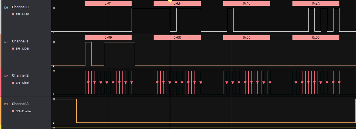
Working Capture for reading ID

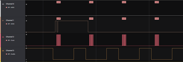
My code output Capture 

Parents
  • Hello,

    Could you please share your overlay file as we need to check if there are any pins used as overlapping? SPI shares registers and other resources with other peripherals that have the same ID as the SPI. It is mandatory to disable all peripherals that have the same ID as the SPI before the SPI can be configured and used. So, it has to be made sure that you are not using the pins for other peripherals.

    Thanks.

    Best Regards,

    Kazi Afroza Sultana

Reply
  • Hello,

    Could you please share your overlay file as we need to check if there are any pins used as overlapping? SPI shares registers and other resources with other peripherals that have the same ID as the SPI. It is mandatory to disable all peripherals that have the same ID as the SPI before the SPI can be configured and used. So, it has to be made sure that you are not using the pins for other peripherals.

    Thanks.

    Best Regards,

    Kazi Afroza Sultana

Children
  • /*
     * Copyright (c) 2019 Nordic Semiconductor ASA
     *
     * SPDX-License-Identifier: Apache-2.0
     */
    
    /dts-v1/;
    #include <nordic/nrf52833_qiaa.dtsi>
    #include "nrf52833dk_nrf52833-pinctrl.dtsi"
    
    / {
    	model = "Nordic nRF52833 DK NRF52833";
    	compatible = "nordic,nrf52833-dk-nrf52833";
    
    	chosen {
    		zephyr,console = &uart0;
    		zephyr,shell-uart = &uart0;
    		zephyr,uart-mcumgr = &uart0;
    		zephyr,bt-mon-uart = &uart0;
    		zephyr,bt-c2h-uart = &uart0;
    		zephyr,sram = &sram0;
    		zephyr,flash = &flash0;
    		zephyr,code-partition = &slot0_partition;
    	};
    
    	leds {
    		compatible = "gpio-leds";
    		led0: led_0 {
    			gpios = <&gpio0 13 GPIO_ACTIVE_LOW>;
    			label = "Green LED 0";
    		};
    		led1: led_1 {
    			gpios = <&gpio0 14 GPIO_ACTIVE_LOW>;
    			label = "Green LED 1";
    		};
    		led2: led_2 {
    			gpios = <&gpio0 15 GPIO_ACTIVE_LOW>;
    			label = "Green LED 2";
    		};
    		led3: led_3 {
    			gpios = <&gpio0 16 GPIO_ACTIVE_LOW>;
    			label = "Green LED 3";
    		};
    	};
    
    	pwmleds {
    		compatible = "pwm-leds";
    		pwm_led0: pwm_led_0 {
    			pwms = <&pwm0 0 PWM_MSEC(20) PWM_POLARITY_INVERTED>;
    		};
    	};
    
    	buttons {
    		compatible = "gpio-keys";
    		button0: button_0 {
    			gpios = <&gpio0 11 (GPIO_PULL_UP | GPIO_ACTIVE_LOW)>;
    			label = "Push button switch 0";
    		};
    		button1: button_1 {
    			gpios = <&gpio0 12 (GPIO_PULL_UP | GPIO_ACTIVE_LOW)>;
    			label = "Push button switch 1";
    		};
    		button2: button_2 {
    			gpios = <&gpio0 24 (GPIO_PULL_UP | GPIO_ACTIVE_LOW)>;
    			label = "Push button switch 2";
    		};
    		button3: button_3 {
    			gpios = <&gpio0 25 (GPIO_PULL_UP | GPIO_ACTIVE_LOW)>;
    			label = "Push button switch 3";
    		};
    	};
    
    	arduino_header: connector {
    		compatible = "arduino-header-r3";
    		#gpio-cells = <2>;
    		gpio-map-mask = <0xffffffff 0xffffffc0>;
    		gpio-map-pass-thru = <0 0x3f>;
    		gpio-map = <0 0 &gpio0 3 0>,	/* A0 */
    			   <1 0 &gpio0 4 0>,	/* A1 */
    			   <2 0 &gpio0 28 0>,	/* A2 */
    			   <3 0 &gpio0 29 0>,	/* A3 */
    			   <4 0 &gpio0 30 0>,	/* A4 */
    			   <5 0 &gpio0 31 0>,	/* A5 */
    			   <6 0 &gpio1 1 0>,	/* D0 */
    			   <7 0 &gpio1 2 0>,	/* D1 */
    			   <8 0 &gpio1 3 0>,	/* D2 */
    			   <9 0 &gpio1 4 0>,	/* D3 */
    			   <10 0 &gpio1 5 0>,	/* D4 */
    			   <11 0 &gpio1 6 0>,	/* D5 */
    			   <12 0 &gpio1 7 0>,	/* D6 */
    			   <13 0 &gpio1 8 0>,	/* D7 */
    			   <14 0 &gpio0 17 0>,	/* D8 */
    			   <15 0 &gpio0 19 0>,	/* D9 */
    			   <16 0 &gpio0 20 0>,	/* D10 */
    			   <17 0 &gpio0 21 0>,	/* D11 */
    			   <18 0 &gpio0 22 0>,	/* D12 */
    			   <19 0 &gpio0 23 0>,	/* D13 */
    			   <20 0 &gpio0 26 0>,	/* D14 */
    			   <21 0 &gpio0 27 0>;	/* D15 */
    	};
    
    	/* These aliases are provided for compatibility with samples */
    	aliases {
    		led0 = &led0;
    		led1 = &led1;
    		//led2 = &led2;
    		led3 = &led3;
    		pwm-led0 = &pwm_led0;
    		sw0 = &button0;
    		sw1 = &button1;
    		sw2 = &button2;
    		sw3 = &button3;
    		bootloader-led0 = &led0;
    	};
    };
    
    &adc {
    	status = "okay";
    };
    
    &gpiote {
    	status = "okay";
    };
    
    &gpio0 {
    	status = "okay";
    };
    
    &gpio1 {
    	status = "okay";
    };
    
    &uart0 {
    	compatible = "nordic,nrf-uarte";
    	status = "okay";
    	current-speed = <115200>;
    	pinctrl-0 = <&uart0_default>;
    	pinctrl-1 = <&uart0_sleep>;
    	pinctrl-names = "default", "sleep";
    };
    
    arduino_serial: &uart1 {
    	status = "okay";
    	current-speed = <115200>;
    	pinctrl-0 = <&uart1_default>;
    	pinctrl-1 = <&uart1_sleep>;
    	pinctrl-names = "default", "sleep";
    };
    
    arduino_i2c: &i2c0 {
    	compatible = "nordic,nrf-twi";
    	status = "okay";
    	pinctrl-0 = <&i2c0_default>;
    	pinctrl-1 = <&i2c0_sleep>;
    	pinctrl-names = "default", "sleep";
    };
    
    &i2c1 {
    	compatible = "nordic,nrf-twi";
    	/* Cannot be used together with spi1. */
    	/* status = "okay"; */
    	pinctrl-0 = <&i2c1_default>;
    	pinctrl-1 = <&i2c1_sleep>;
    	pinctrl-names = "default", "sleep";
    };
    
    &pwm0 {
    	status = "okay";
    	pinctrl-0 = <&pwm0_default>;
    	pinctrl-1 = <&pwm0_sleep>;
    	pinctrl-names = "default", "sleep";
    };
    
    &spi0 {
    	compatible = "nordic,nrf-spi";
    	/* Cannot be used together with i2c0. */
    	/* status = "okay"; */
    	pinctrl-0 = <&spi0_default>;
    	pinctrl-1 = <&spi0_sleep>;
    	pinctrl-names = "default", "sleep";
    };
    
    &spi1 {
    	compatible = "nordic,nrf-spi";
    	status = "okay";
    	//pinctrl-0 = <&spi1_default>;
    	//pinctrl-1 = <&spi1_sleep>;
    	cs-gpios = <&gpio0  20 GPIO_ACTIVE_LOW>; /* D10 */
    	pinctrl-0 = <&spi3_default>;
    	pinctrl-1 = <&spi3_sleep>;
    	pinctrl-names = "default", "sleep";
    	label = "SPI_1";
    };
    
    // arduino_spi: &spi3 {
    // 	status = "okay";
    // 	cs-gpios = <&gpio0  20 GPIO_ACTIVE_LOW>; /* D10 */
    // 	pinctrl-0 = <&spi3_default>;
    // 	pinctrl-1 = <&spi3_sleep>;
    // 	pinctrl-names = "default", "sleep";
    // };
    
    &flash0 {
    
    	partitions {
    		compatible = "fixed-partitions";
    		#address-cells = <1>;
    		#size-cells = <1>;
    
    		boot_partition: partition@0 {
    			label = "mcuboot";
    			reg = <0x000000000 0xC000>;
    		};
    		slot0_partition: partition@c000 {
    			label = "image-0";
    			reg = <0x0000C000 0x32000>;
    		};
    		slot1_partition: partition@3e000 {
    			label = "image-1";
    			reg = <0x0003E000 0x32000>;
    		};
    		scratch_partition: partition@70000 {
    			label = "image-scratch";
    			reg = <0x00070000 0xA000>;
    		};
    		storage_partition: partition@7a000 {
    			label = "storage";
    			reg = <0x0007A000 0x00006000>;
    		};
    	};
    };
    
    zephyr_udc0: &usbd {
    	compatible = "nordic,nrf-usbd";
    	status = "okay";
    };
    

    this is it.

  • Hello,

    Here is in your dts fiile, we can see for example, the default pins for SPI3 

    &spi1 {
    compatible = "nordic,nrf-spi";
    status = "okay";
    //pinctrl-0 = <&spi1_default>;
    //pinctrl-1 = <&spi1_sleep>;
    cs-gpios = <&gpio0 20 GPIO_ACTIVE_LOW>; /* D10 */
    pinctrl-0 = <&spi3_default>;
    pinctrl-1 = <&spi3_sleep>;
    pinctrl-names = "default", "sleep";
    label = "SPI_1";
    };

    should be 21 for MOSI, 22 for MISO and 23 for SCK. However, it cannot be assured only looking at this file. So, we would need to look into the device tree from build output to see what is assigned to what. 

    BR

    Kazi

  • Hi , Yes you assumed correctly .I had disabled other peripherals for this.

  • Yes. So, you can send the device tree from build output to us so that we can check and also code snippet where these pin configurations are shown. 

  • Hi , so I have been able to get some response from the flash (not correct), 

    I wanna know , how can I change the spi modes

    i.e. - CPOL &CPHA 

    2nd 

    how can i use spi without including a CS pin configuration, I am using a gpio as cs pin. 

Related