


hi,
I want to use PPI function for timer trigger to PWM, but I noticed PWM doesn't have TASK_START register, please see the pictures.
how can I start PWM by timer?
thanks 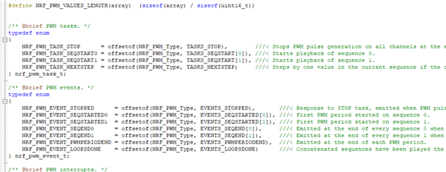
hi,
I want to use PPI function for timer trigger to PWM, but I noticed PWM doesn't have TASK_START register, please see the pictures.
how can I start PWM by timer?
thanks
Hi,
As you can read in the PWM peripheral documentation, each PWM instance can set two separate sequences, SEQ[0] and SEQ[1]. These are started using TASKS_SEQSTART[0] and TASKS_SEQSTART[1]. See Figure 7 for a sequence diagram of the simplest PWM operation.
Best regards,
Jørgen

What are you trying to achieve? It is possible to assign a second task to be triggered by a PPI channel using the FORK, but I can't see why you would want to trigger both tasks at once. You can configure the PWM peripheral to play the sequences after each other by setting the LOOP and SEQ[n].CNT registers, see figure 6 and the code above in PWM peripheral documentation. If you want to trigger both SEQSTART tasks at different times, you need to use two separate PPI channels.
I only want to start two PWM synchronously, no delay time, so I will use PPI, and every PWM used complex playback function, SEQ[0] and SEQ[1] have data too.
So I want to know how to trigger PWM by PPI, but PWM doesn't have TASK_START register as TIMER, you said only start TASKS_SEQSTART[0] and TASKS_SEQSTART[1] for PWM, these two registers needn't start synchronously.
could you tell me how to trigger PWM by PPI?
You can't start both sequences at the same time. If you want to generate two separate PWM signals and need them to be synchronized, you can use two separate PWM instances and start each of them (through one of the TASKS_SEQSTART[n] registers) from a PPI channel with a fork. It is also possible to use two separate PPI channels and trigger them both from the same timer EVENT.
You can't start both sequences at the same time. If you want to generate two separate PWM signals and need them to be synchronized, you can use two separate PWM instances and start each of them (through one of the TASKS_SEQSTART[n] registers) from a PPI channel with a fork. It is also possible to use two separate PPI channels and trigger them both from the same timer EVENT.
could you see my code? I write "NRF_PWM_TASK_SEQSTART0", it does not start. but I write "NRF_PWM_TASK_STOP", it can stop PWM normally. So I think the PWM start register is wrong. where should I change it.
Thanks
void timer0_event_handler(nrf_timer_event_t event_type, void* p_context)
{
	nrf_drv_pwm_uninit(&m_pwm1);
	r0=1;r1=1;Count_Ring0=0,Count_Ring1=1;
	nrf_drv_pwm_uninit(&m_pwm0);
	t0=1;t1=1;Count_Tip0=0,Count_Tip1=1;

}
static void ppi_init(void)
{
uint32_t err_code = NRF_SUCCESS;
err_code = nrf_drv_ppi_init();
APP_ERROR_CHECK(err_code);
err_code = nrf_drv_ppi_channel_alloc(&m_ppi_channel1);
APP_ERROR_CHECK(err_code);
err_code = nrf_drv_ppi_channel_assign(m_ppi_channel1,
nrf_drv_timer_event_address_get(&m_timer0,
NRF_TIMER_EVENT_COMPARE0),
nrf_drv_pwm_task_address_get(&m_pwm0,
NRF_PWM_TASK_SEQSTART0));
APP_ERROR_CHECK(err_code);
err_code = nrf_drv_ppi_channel_fork_assign(m_ppi_channel1,
nrf_drv_pwm_task_address_get(&m_pwm1,
NRF_PWM_TASK_SEQSTART0));
APP_ERROR_CHECK(err_code);
err_code = nrf_drv_ppi_channel_enable(m_ppi_channel1);
APP_ERROR_CHECK(err_code);
}
static void PWM_init(void)
{
seq_values_Tip0[0] = seq_values_Tip[Count_Tip0];
seq_values_Tip1[0] = seq_values_Tip[Count_Tip1];
seq_values_Ring0[0] = seq_values_Ring[Count_Ring0];
seq_values_Ring1[0] = seq_values_Ring[Count_Ring1];
nrf_drv_pwm_config_t const configTip0 =
{
.output_pins =
{
BSP_LED_1 | NRF_DRV_PWM_PIN_INVERTED, // channel 0
NRF_DRV_PWM_PIN_NOT_USED, // channel 1
NRF_DRV_PWM_PIN_NOT_USED, // channel 2
NRF_DRV_PWM_PIN_NOT_USED, // channel 3
},
.irq_priority = APP_IRQ_PRIORITY_LOWEST,
.base_clock = NRF_PWM_CLK_16MHz,
.count_mode = NRF_PWM_MODE_UP,
.top_value = 0,
.load_mode = NRF_PWM_LOAD_WAVE_FORM,
.step_mode = NRF_PWM_STEP_AUTO
};
nrf_drv_pwm_config_t const configRing0 =
{
.output_pins =
{
BSP_LED_0 | NRF_DRV_PWM_PIN_INVERTED, // channel 0
NRF_DRV_PWM_PIN_NOT_USED, // channel 1
NRF_DRV_PWM_PIN_NOT_USED, // channel 2
NRF_DRV_PWM_PIN_NOT_USED, // channel 3
},
.irq_priority = APP_IRQ_PRIORITY_LOWEST,
.base_clock = NRF_PWM_CLK_16MHz,
.count_mode = NRF_PWM_MODE_UP,
.top_value = 0,
.load_mode = NRF_PWM_LOAD_WAVE_FORM,
.step_mode = NRF_PWM_STEP_AUTO
};
ReleasePWM();
// APP_ERROR_CHECK(nrf_drv_pwm_init(&m_pwm0, &configTip0, NULL));
// APP_ERROR_CHECK(nrf_drv_pwm_init(&m_pwm1, &configRing0, NULL));
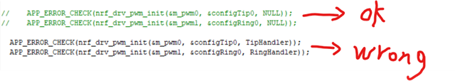
APP_ERROR_CHECK(nrf_drv_pwm_init(&m_pwm0, &configTip0, TipHandler));
APP_ERROR_CHECK(nrf_drv_pwm_init(&m_pwm1, &configRing0, RingHandler));
m_used |= USED_PWM(0);
m_used |= USED_PWM(1);
nrf_pwm_sequence_t const seq_Tip0 =
{
.values.p_wave_form = seq_values_Tip0,
.length = NRF_PWM_VALUES_LENGTH(seq_values_Tip0),
.repeats = number_Tip[Count_Tip0]-1,
.end_delay = 0
};
nrf_pwm_sequence_t const seq_Tip1 =
{
.values.p_wave_form = seq_values_Tip1,
.length = NRF_PWM_VALUES_LENGTH(seq_values_Tip1),
.repeats = number_Tip[Count_Tip1]-1,
.end_delay = 0
};
nrf_pwm_sequence_t const seq_Ring0 =
{
.values.p_wave_form = seq_values_Ring0,
.length = NRF_PWM_VALUES_LENGTH(seq_values_Ring0),
.repeats = number_Ring[Count_Ring0]-1,
.end_delay = 0
};
nrf_pwm_sequence_t const seq_Ring1 =
{
.values.p_wave_form = seq_values_Ring1,
.length = NRF_PWM_VALUES_LENGTH(seq_values_Ring1),
.repeats = number_Ring[Count_Ring1]-1,
.end_delay = 0
};
// (void)nrf_drv_pwm_simple_playback(&m_pwm0, &seq_Tip0, 1, NRFX_PWM_FLAG_LOOP);
// (void)nrf_drv_pwm_simple_playback(&m_pwm1, &seq_Ring0, 1, NRFX_PWM_FLAG_LOOP);
// (void)nrf_drv_pwm_complex_playback(&m_pwm0, &seq_Tip0, &seq_Tip1, (Tip_Number/2+1), NRFX_PWM_FLAG_STOP|NRF_DRV_PWM_FLAG_SIGNAL_END_SEQ0 |NRF_DRV_PWM_FLAG_SIGNAL_END_SEQ1);
// (void)nrf_drv_pwm_complex_playback(&m_pwm1, &seq_Ring0, &seq_Ring1, (Ring_Number/2+1), NRFX_PWM_FLAG_STOP|NRF_DRV_PWM_FLAG_SIGNAL_END_SEQ0 |NRF_DRV_PWM_FLAG_SIGNAL_END_SEQ1);
//
uint32_t start_pwm0_task_addr = nrf_drv_pwm_complex_playback(&m_pwm0, &seq_Tip0, &seq_Tip1, (Tip_Number/2+1), NRFX_PWM_FLAG_STOP | NRF_DRV_PWM_FLAG_START_VIA_TASK|NRF_DRV_PWM_FLAG_SIGNAL_END_SEQ0 | NRF_DRV_PWM_FLAG_SIGNAL_END_SEQ1);
uint32_t *start_pwm0_task = (uint32_t *) start_pwm0_task_addr;
//start_pwm0_task = (uint32_t *) start_pwm0_task_addr;
uint32_t start_pwm1_task_addr = nrf_drv_pwm_complex_playback(&m_pwm1, &seq_Ring0, &seq_Ring1, (Ring_Number/2+1), NRFX_PWM_FLAG_STOP | NRF_DRV_PWM_FLAG_START_VIA_TASK|NRF_DRV_PWM_FLAG_SIGNAL_END_SEQ0 | NRF_DRV_PWM_FLAG_SIGNAL_END_SEQ1);
uint32_t *start_pwm1_task = (uint32_t *) start_pwm1_task_addr;
//start_pwm1_task = (uint32_t *) start_pwm1_task_addr;
*start_pwm0_task = 1;
*start_pwm1_task = 1;
}
Your code looks correct to me. Do none of the PWM channels start, or only one of them?
Do the PWM channels start if you trigger TASKS_SEQSTART[0] from code?
It looks like you also start the sequence from your code using the driver, have you tried to run the code without this?
Have you checked if the value returned by nrf_drv_pwm_complex_playback() and nrf_drv_pwm_task_address_get(&m_pwm0, NRF_PWM_TASK_SEQSTART0) is the same?
Have you verified that the timer is running correctly, and that the event from the timer is actually generated?
yes, I think it is PWM interrupt wrong, when I close SEQ[0] and SEQ[1] interrupt, PWM1 and PWM0 will be synchronized, but if I use SEQ[0] and SEQ[1] interrupt, it will be wrong, please see my code and picture.Could you tell me where I should change it. static void TipHandler(nrfx_pwm_evt_type_t event_type)
{
if (event_type == NRFX_PWM_EVT_END_SEQ0)
{
Count_Tip0 = Count_Tip0+2;
seq_values_Tip0[0] = seq_values_Tip[Count_Tip0];
NRF_PWM0->SEQ[0].REFRESH = number_Tip[Count_Tip0]-1;
t0++;
}
if (event_type == NRFX_PWM_EVT_END_SEQ1)
{
Count_Tip1 = Count_Tip1+2;
seq_values_Tip1[0] = seq_values_Tip[Count_Tip1];
NRF_PWM0->SEQ[1].REFRESH = number_Tip[Count_Tip1]-1;
t1++;
if(t1>(Tip_Number/2))
{
NRF_PWM0->TASKS_STOP = 1;
t0=1;t1=1;Count_Tip0=0,Count_Tip1=1;
return;
}
}
}
static void RingHandler(nrfx_pwm_evt_type_t event_type)
{
if (event_type == NRFX_PWM_EVT_END_SEQ0)
{
Count_Ring0 = Count_Ring0+2;
seq_values_Ring0[0] = seq_values_Ring[Count_Ring0];
NRF_PWM1->SEQ[0].REFRESH = number_Ring[Count_Ring0]-1;
r0++;
}
if (event_type == NRFX_PWM_EVT_END_SEQ1)
{
Count_Ring1 = Count_Ring1+2;
seq_values_Ring1[0] = seq_values_Ring[Count_Ring1];
NRF_PWM1->SEQ[1].REFRESH = number_Ring[Count_Ring1]-1;
r1++;
if(r1>(Ring_Number/2))
{
NRF_PWM1->TASKS_STOP = 1;
r0=1;r1=1;Count_Ring0=0,Count_Ring1=1;
return;
}
}
}
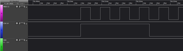
the wrong wave picture, only has PWM0 wave, and PWM1 disappear.
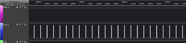
the right wave picture, PWM0 wave and PWM1 are synchronized.