hi,
I want to use PPI function for timer trigger to PWM, but I noticed PWM doesn't have TASK_START register, please see the pictures.
how can I start PWM by timer?
thanks 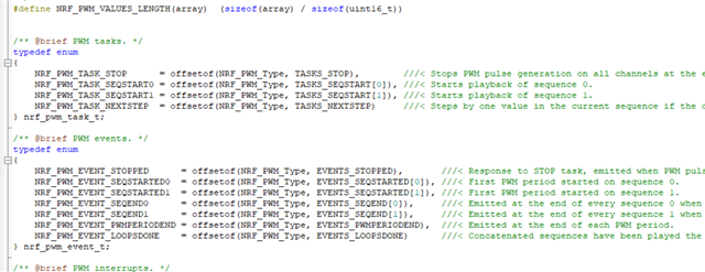
hi,
I want to use PPI function for timer trigger to PWM, but I noticed PWM doesn't have TASK_START register, please see the pictures.
how can I start PWM by timer?
thanks
Hi,
As you can read in the PWM peripheral documentation, each PWM instance can set two separate sequences, SEQ[0] and SEQ[1]. These are started using TASKS_SEQSTART[0] and TASKS_SEQSTART[1]. See Figure 7 for a sequence diagram of the simplest PWM operation.
Best regards,
Jørgen

What are you trying to achieve? It is possible to assign a second task to be triggered by a PPI channel using the FORK, but I can't see why you would want to trigger both tasks at once. You can configure the PWM peripheral to play the sequences after each other by setting the LOOP and SEQ[n].CNT registers, see figure 6 and the code above in PWM peripheral documentation. If you want to trigger both SEQSTART tasks at different times, you need to use two separate PPI channels.
I only want to start two PWM synchronously, no delay time, so I will use PPI, and every PWM used complex playback function, SEQ[0] and SEQ[1] have data too.
So I want to know how to trigger PWM by PPI, but PWM doesn't have TASK_START register as TIMER, you said only start TASKS_SEQSTART[0] and TASKS_SEQSTART[1] for PWM, these two registers needn't start synchronously.
could you tell me how to trigger PWM by PPI?
You can't start both sequences at the same time. If you want to generate two separate PWM signals and need them to be synchronized, you can use two separate PWM instances and start each of them (through one of the TASKS_SEQSTART[n] registers) from a PPI channel with a fork. It is also possible to use two separate PPI channels and trigger them both from the same timer EVENT.
could you see my code? I write "NRF_PWM_TASK_SEQSTART0", it does not start. but I write "NRF_PWM_TASK_STOP", it can stop PWM normally. So I think the PWM start register is wrong. where should I change it.
Thanks
void timer0_event_handler(nrf_timer_event_t event_type, void* p_context)
{
	nrf_drv_pwm_uninit(&m_pwm1);
	r0=1;r1=1;Count_Ring0=0,Count_Ring1=1;
	nrf_drv_pwm_uninit(&m_pwm0);
	t0=1;t1=1;Count_Tip0=0,Count_Tip1=1;

}
static void ppi_init(void)
{
uint32_t err_code = NRF_SUCCESS;
err_code = nrf_drv_ppi_init();
APP_ERROR_CHECK(err_code);
err_code = nrf_drv_ppi_channel_alloc(&m_ppi_channel1);
APP_ERROR_CHECK(err_code);
err_code = nrf_drv_ppi_channel_assign(m_ppi_channel1,
nrf_drv_timer_event_address_get(&m_timer0,
NRF_TIMER_EVENT_COMPARE0),
nrf_drv_pwm_task_address_get(&m_pwm0,
NRF_PWM_TASK_SEQSTART0));
APP_ERROR_CHECK(err_code);
err_code = nrf_drv_ppi_channel_fork_assign(m_ppi_channel1,
nrf_drv_pwm_task_address_get(&m_pwm1,
NRF_PWM_TASK_SEQSTART0));
APP_ERROR_CHECK(err_code);
err_code = nrf_drv_ppi_channel_enable(m_ppi_channel1);
APP_ERROR_CHECK(err_code);
}
static void PWM_init(void)
{
seq_values_Tip0[0] = seq_values_Tip[Count_Tip0];
seq_values_Tip1[0] = seq_values_Tip[Count_Tip1];
seq_values_Ring0[0] = seq_values_Ring[Count_Ring0];
seq_values_Ring1[0] = seq_values_Ring[Count_Ring1];
nrf_drv_pwm_config_t const configTip0 =
{
.output_pins =
{
BSP_LED_1 | NRF_DRV_PWM_PIN_INVERTED, // channel 0
NRF_DRV_PWM_PIN_NOT_USED, // channel 1
NRF_DRV_PWM_PIN_NOT_USED, // channel 2
NRF_DRV_PWM_PIN_NOT_USED, // channel 3
},
.irq_priority = APP_IRQ_PRIORITY_LOWEST,
.base_clock = NRF_PWM_CLK_16MHz,
.count_mode = NRF_PWM_MODE_UP,
.top_value = 0,
.load_mode = NRF_PWM_LOAD_WAVE_FORM,
.step_mode = NRF_PWM_STEP_AUTO
};
nrf_drv_pwm_config_t const configRing0 =
{
.output_pins =
{
BSP_LED_0 | NRF_DRV_PWM_PIN_INVERTED, // channel 0
NRF_DRV_PWM_PIN_NOT_USED, // channel 1
NRF_DRV_PWM_PIN_NOT_USED, // channel 2
NRF_DRV_PWM_PIN_NOT_USED, // channel 3
},
.irq_priority = APP_IRQ_PRIORITY_LOWEST,
.base_clock = NRF_PWM_CLK_16MHz,
.count_mode = NRF_PWM_MODE_UP,
.top_value = 0,
.load_mode = NRF_PWM_LOAD_WAVE_FORM,
.step_mode = NRF_PWM_STEP_AUTO
};
ReleasePWM();
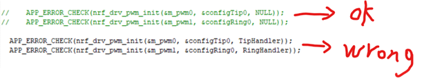
// APP_ERROR_CHECK(nrf_drv_pwm_init(&m_pwm0, &configTip0, NULL));
// APP_ERROR_CHECK(nrf_drv_pwm_init(&m_pwm1, &configRing0, NULL));
APP_ERROR_CHECK(nrf_drv_pwm_init(&m_pwm0, &configTip0, TipHandler));
APP_ERROR_CHECK(nrf_drv_pwm_init(&m_pwm1, &configRing0, RingHandler));
m_used |= USED_PWM(0);
m_used |= USED_PWM(1);
nrf_pwm_sequence_t const seq_Tip0 =
{
.values.p_wave_form = seq_values_Tip0,
.length = NRF_PWM_VALUES_LENGTH(seq_values_Tip0),
.repeats = number_Tip[Count_Tip0]-1,
.end_delay = 0
};
nrf_pwm_sequence_t const seq_Tip1 =
{
.values.p_wave_form = seq_values_Tip1,
.length = NRF_PWM_VALUES_LENGTH(seq_values_Tip1),
.repeats = number_Tip[Count_Tip1]-1,
.end_delay = 0
};
nrf_pwm_sequence_t const seq_Ring0 =
{
.values.p_wave_form = seq_values_Ring0,
.length = NRF_PWM_VALUES_LENGTH(seq_values_Ring0),
.repeats = number_Ring[Count_Ring0]-1,
.end_delay = 0
};
nrf_pwm_sequence_t const seq_Ring1 =
{
.values.p_wave_form = seq_values_Ring1,
.length = NRF_PWM_VALUES_LENGTH(seq_values_Ring1),
.repeats = number_Ring[Count_Ring1]-1,
.end_delay = 0
};
// (void)nrf_drv_pwm_simple_playback(&m_pwm0, &seq_Tip0, 1, NRFX_PWM_FLAG_LOOP);
// (void)nrf_drv_pwm_simple_playback(&m_pwm1, &seq_Ring0, 1, NRFX_PWM_FLAG_LOOP);
// (void)nrf_drv_pwm_complex_playback(&m_pwm0, &seq_Tip0, &seq_Tip1, (Tip_Number/2+1), NRFX_PWM_FLAG_STOP|NRF_DRV_PWM_FLAG_SIGNAL_END_SEQ0 |NRF_DRV_PWM_FLAG_SIGNAL_END_SEQ1);
// (void)nrf_drv_pwm_complex_playback(&m_pwm1, &seq_Ring0, &seq_Ring1, (Ring_Number/2+1), NRFX_PWM_FLAG_STOP|NRF_DRV_PWM_FLAG_SIGNAL_END_SEQ0 |NRF_DRV_PWM_FLAG_SIGNAL_END_SEQ1);
//
uint32_t start_pwm0_task_addr = nrf_drv_pwm_complex_playback(&m_pwm0, &seq_Tip0, &seq_Tip1, (Tip_Number/2+1), NRFX_PWM_FLAG_STOP | NRF_DRV_PWM_FLAG_START_VIA_TASK|NRF_DRV_PWM_FLAG_SIGNAL_END_SEQ0 | NRF_DRV_PWM_FLAG_SIGNAL_END_SEQ1);
uint32_t *start_pwm0_task = (uint32_t *) start_pwm0_task_addr;
//start_pwm0_task = (uint32_t *) start_pwm0_task_addr;
uint32_t start_pwm1_task_addr = nrf_drv_pwm_complex_playback(&m_pwm1, &seq_Ring0, &seq_Ring1, (Ring_Number/2+1), NRFX_PWM_FLAG_STOP | NRF_DRV_PWM_FLAG_START_VIA_TASK|NRF_DRV_PWM_FLAG_SIGNAL_END_SEQ0 | NRF_DRV_PWM_FLAG_SIGNAL_END_SEQ1);
uint32_t *start_pwm1_task = (uint32_t *) start_pwm1_task_addr;
//start_pwm1_task = (uint32_t *) start_pwm1_task_addr;
*start_pwm0_task = 1;
*start_pwm1_task = 1;
}
static void ppi_init(void)
{
    uint32_t err_code = NRF_SUCCESS;

    err_code = nrf_drv_ppi_init();
    APP_ERROR_CHECK(err_code);

    err_code = nrf_drv_ppi_channel_alloc(&m_ppi_channel1);
    APP_ERROR_CHECK(err_code);
    err_code = nrf_drv_ppi_channel_assign(m_ppi_channel1,
                                          nrf_drv_timer_event_address_get(&m_timer0,
                                                                          NRF_TIMER_EVENT_COMPARE0),
                                          nrf_drv_pwm_task_address_get(&m_pwm0,
                                                                         NRF_PWM_TASK_SEQSTART0));
    APP_ERROR_CHECK(err_code);

		err_code = nrf_drv_ppi_channel_fork_assign(m_ppi_channel1,
                                          nrf_drv_pwm_task_address_get(&m_pwm1,
                                                                         NRF_PWM_TASK_SEQSTART0));
    APP_ERROR_CHECK(err_code);


    err_code = nrf_drv_ppi_channel_enable(m_ppi_channel1);
    APP_ERROR_CHECK(err_code);
}


static void PWM_init(void)
{

	seq_values_Tip0[0] = seq_values_Tip[Count_Tip0];
	seq_values_Tip1[0] = seq_values_Tip[Count_Tip1];

	seq_values_Ring0[0] = seq_values_Ring[Count_Ring0];
	seq_values_Ring1[0] = seq_values_Ring[Count_Ring1];

	nrf_drv_pwm_config_t const configTip0 =
	{
			.output_pins =
			{
					BSP_LED_1 | NRF_DRV_PWM_PIN_INVERTED, // channel 0
					NRF_DRV_PWM_PIN_NOT_USED,             // channel 1
					NRF_DRV_PWM_PIN_NOT_USED,             // channel 2
					NRF_DRV_PWM_PIN_NOT_USED,             // channel 3
			},
			.irq_priority = APP_IRQ_PRIORITY_LOWEST,
			.base_clock   = NRF_PWM_CLK_16MHz,
			.count_mode   = NRF_PWM_MODE_UP,
			.top_value    = 0,
			.load_mode    = NRF_PWM_LOAD_WAVE_FORM,
			.step_mode    = NRF_PWM_STEP_AUTO
	};
	nrf_drv_pwm_config_t const configRing0 =
	{
			.output_pins =
			{
					BSP_LED_0 | NRF_DRV_PWM_PIN_INVERTED, // channel 0
					NRF_DRV_PWM_PIN_NOT_USED,             // channel 1
					NRF_DRV_PWM_PIN_NOT_USED,             // channel 2
					NRF_DRV_PWM_PIN_NOT_USED,             // channel 3
			},
			.irq_priority = APP_IRQ_PRIORITY_LOWEST,
			.base_clock   = NRF_PWM_CLK_16MHz,
			.count_mode   = NRF_PWM_MODE_UP,
			.top_value    = 0,
			.load_mode    = NRF_PWM_LOAD_WAVE_FORM,
			.step_mode    = NRF_PWM_STEP_AUTO
	};

	ReleasePWM();

//    APP_ERROR_CHECK(nrf_drv_pwm_init(&m_pwm0, &configTip0, NULL));
//    APP_ERROR_CHECK(nrf_drv_pwm_init(&m_pwm1, &configRing0, NULL));

	APP_ERROR_CHECK(nrf_drv_pwm_init(&m_pwm0, &configTip0, TipHandler));
	APP_ERROR_CHECK(nrf_drv_pwm_init(&m_pwm1, &configRing0, RingHandler));


	m_used |= USED_PWM(0);
	m_used |= USED_PWM(1);

	nrf_pwm_sequence_t const seq_Tip0 =
	{
			.values.p_wave_form = seq_values_Tip0,
			.length          = NRF_PWM_VALUES_LENGTH(seq_values_Tip0),
			.repeats         = number_Tip[Count_Tip0]-1,
			.end_delay       = 0
	};

	 nrf_pwm_sequence_t const seq_Tip1 =
	{
			.values.p_wave_form = seq_values_Tip1,
			.length          = NRF_PWM_VALUES_LENGTH(seq_values_Tip1),
			.repeats         = number_Tip[Count_Tip1]-1,
			.end_delay       = 0
	};

	nrf_pwm_sequence_t const seq_Ring0 =
	{
			.values.p_wave_form = seq_values_Ring0,
			.length          = NRF_PWM_VALUES_LENGTH(seq_values_Ring0),
			.repeats         = number_Ring[Count_Ring0]-1,
			.end_delay       = 0
	};

	nrf_pwm_sequence_t const seq_Ring1 =
	{
			.values.p_wave_form = seq_values_Ring1,
			.length          = NRF_PWM_VALUES_LENGTH(seq_values_Ring1),
			.repeats         = number_Ring[Count_Ring1]-1,
			.end_delay       = 0
	};


//    (void)nrf_drv_pwm_simple_playback(&m_pwm0, &seq_Tip0, 1, NRFX_PWM_FLAG_LOOP);
//    (void)nrf_drv_pwm_simple_playback(&m_pwm1, &seq_Ring0, 1, NRFX_PWM_FLAG_LOOP);


//	(void)nrf_drv_pwm_complex_playback(&m_pwm0, &seq_Tip0, &seq_Tip1, (Tip_Number/2+1), NRFX_PWM_FLAG_STOP|NRF_DRV_PWM_FLAG_SIGNAL_END_SEQ0 |NRF_DRV_PWM_FLAG_SIGNAL_END_SEQ1);
//	(void)nrf_drv_pwm_complex_playback(&m_pwm1, &seq_Ring0, &seq_Ring1, (Ring_Number/2+1), NRFX_PWM_FLAG_STOP|NRF_DRV_PWM_FLAG_SIGNAL_END_SEQ0 |NRF_DRV_PWM_FLAG_SIGNAL_END_SEQ1);
//

	uint32_t start_pwm0_task_addr = nrf_drv_pwm_complex_playback(&m_pwm0, &seq_Tip0, &seq_Tip1, (Tip_Number/2+1), NRFX_PWM_FLAG_STOP | NRF_DRV_PWM_FLAG_START_VIA_TASK|NRF_DRV_PWM_FLAG_SIGNAL_END_SEQ0 | NRF_DRV_PWM_FLAG_SIGNAL_END_SEQ1);
	uint32_t *start_pwm0_task = (uint32_t *) start_pwm0_task_addr;
  //start_pwm0_task = (uint32_t *) start_pwm0_task_addr;

	uint32_t start_pwm1_task_addr = nrf_drv_pwm_complex_playback(&m_pwm1, &seq_Ring0, &seq_Ring1, (Ring_Number/2+1), NRFX_PWM_FLAG_STOP | NRF_DRV_PWM_FLAG_START_VIA_TASK|NRF_DRV_PWM_FLAG_SIGNAL_END_SEQ0 | NRF_DRV_PWM_FLAG_SIGNAL_END_SEQ1);
	uint32_t *start_pwm1_task = (uint32_t *) start_pwm1_task_addr;
  //start_pwm1_task = (uint32_t *) start_pwm1_task_addr;

	*start_pwm0_task = 1;
	*start_pwm1_task = 1;
}
Your code looks correct to me. Do none of the PWM channels start, or only one of them?
Do the PWM channels start if you trigger TASKS_SEQSTART[0] from code?
It looks like you also start the sequence from your code using the driver, have you tried to run the code without this?
Have you checked if the value returned by nrf_drv_pwm_complex_playback() and nrf_drv_pwm_task_address_get(&m_pwm0, NRF_PWM_TASK_SEQSTART0) is the same?
Have you verified that the timer is running correctly, and that the event from the timer is actually generated?
yes, I think it is PWM interrupt wrong, when I close SEQ[0] and SEQ[1] interrupt, PWM1 and PWM0 will be synchronized, but if I use SEQ[0] and SEQ[1] interrupt, it will be wrong, please see my code and picture.Could you tell me where I should change it. static void TipHandler(nrfx_pwm_evt_type_t event_type)
{
if (event_type == NRFX_PWM_EVT_END_SEQ0)
{
Count_Tip0 = Count_Tip0+2;
seq_values_Tip0[0] = seq_values_Tip[Count_Tip0];
NRF_PWM0->SEQ[0].REFRESH = number_Tip[Count_Tip0]-1;
t0++;
}
if (event_type == NRFX_PWM_EVT_END_SEQ1)
{
Count_Tip1 = Count_Tip1+2;
seq_values_Tip1[0] = seq_values_Tip[Count_Tip1];
NRF_PWM0->SEQ[1].REFRESH = number_Tip[Count_Tip1]-1;
t1++;
if(t1>(Tip_Number/2))
{
NRF_PWM0->TASKS_STOP = 1;
t0=1;t1=1;Count_Tip0=0,Count_Tip1=1;
return;
}
}
}
static void RingHandler(nrfx_pwm_evt_type_t event_type)
{
if (event_type == NRFX_PWM_EVT_END_SEQ0)
{
Count_Ring0 = Count_Ring0+2;
seq_values_Ring0[0] = seq_values_Ring[Count_Ring0];
NRF_PWM1->SEQ[0].REFRESH = number_Ring[Count_Ring0]-1;
r0++;
}
if (event_type == NRFX_PWM_EVT_END_SEQ1)
{
Count_Ring1 = Count_Ring1+2;
seq_values_Ring1[0] = seq_values_Ring[Count_Ring1];
NRF_PWM1->SEQ[1].REFRESH = number_Ring[Count_Ring1]-1;
r1++;
if(r1>(Ring_Number/2))
{
NRF_PWM1->TASKS_STOP = 1;
r0=1;r1=1;Count_Ring0=0,Count_Ring1=1;
return;
}
}
}
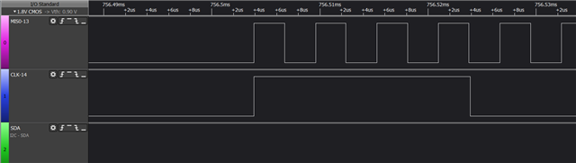
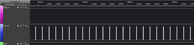
the wrong wave picture, only has PWM0 wave, and PWM1 disappear.
the right wave picture, PWM0 wave and PWM1 are synchronized.
Not sure I understand your pictures. Did you post two of each picture?
Have you debugged the application to see what is triggering the PWM interrupt handler, and if it disables the PWM output somehow?
Could you upload your full application? That would make it easier to reproduce and debug your issue.
#include <stdbool.h>
#include <stdint.h>
#include "nrf.h"
#include "nrf_drv_timer.h"
#include "bsp.h"
#include "app_error.h"
#include "app_uart.h"
#include "nrf_drv_pwm.h"
#include "nrf_drv_ppi.h"
#include "data.h"


#if defined (UART_PRESENT)
#include "nrf_uart.h"
#endif
#if defined (UARTE_PRESENT)
#include "nrf_uarte.h"
#endif

//#define ENABLE_LOOPBACK_TEST  /**< if defined, then this example will be a loopback test, which means that TX should be connected to RX to get data loopback. */

#define MAX_TEST_DATA_BYTES     (15U)                /**< max number of test bytes to be used for tx and rx. */
#define UART_TX_BUF_SIZE 256                         /**< UART TX buffer size. */
#define UART_RX_BUF_SIZE 256                         /**< UART RX buffer size. */

void uart_error_handle(app_uart_evt_t * p_event)
{
    if (p_event->evt_type == APP_UART_COMMUNICATION_ERROR)
    {
        APP_ERROR_HANDLER(p_event->data.error_communication);
    }
    else if (p_event->evt_type == APP_UART_FIFO_ERROR)
    {
        APP_ERROR_HANDLER(p_event->data.error_code);
    }
}


#ifdef ENABLE_LOOPBACK_TEST
/* Use flow control in loopback test. */
#define UART_HWFC APP_UART_FLOW_CONTROL_ENABLED

/** @brief Function for setting the @ref ERROR_PIN high, and then enter an infinite loop.
 */
static void show_error(void)
{

    bsp_board_leds_on();
    while (true)
    {
        // Do nothing.
    }
}


/** @brief Function for testing UART loop back.
 *  @details Transmitts one character at a time to check if the data received from the loopback is same as the transmitted data.
 *  @note  @ref TX_PIN_NUMBER must be connected to @ref RX_PIN_NUMBER)
 */
static void uart_loopback_test()
{
    uint8_t * tx_data = (uint8_t *)("\r\nLOOPBACK_TEST\r\n");
    uint8_t   rx_data;

    // Start sending one byte and see if you get the same
    for (uint32_t i = 0; i < MAX_TEST_DATA_BYTES; i++)
    {
        uint32_t err_code;
        while (app_uart_put(tx_data[i]) != NRF_SUCCESS);

        nrf_delay_ms(10);
        err_code = app_uart_get(&rx_data);

        if ((rx_data != tx_data[i]) || (err_code != NRF_SUCCESS))
        {
            show_error();
        }
    }
    return;
}
#else
/* When UART is used for communication with the host do not use flow control.*/
#define UART_HWFC APP_UART_FLOW_CONTROL_DISABLED
#endif

#define PPI_EXAMPLE_TIMERS_PHASE_SHIFT_DELAY    (10)    // 1s = 10 * 100ms (Timer 0 interrupt)

static volatile uint32_t m_counter;
static const nrf_drv_timer_t m_timer0 = NRF_DRV_TIMER_INSTANCE(0);
static const nrf_drv_timer_t m_timer1 = NRF_DRV_TIMER_INSTANCE(1);
static const nrf_drv_timer_t m_timer2 = NRF_DRV_TIMER_INSTANCE(2);
extern nrf_pwm_values_wave_form_t const seq_values_Ring[];
extern nrf_pwm_values_wave_form_t const seq_values_Tip[];
extern	int  Tip_Number;
extern	int  Ring_Number;
extern	int number_Tip[];
extern	int number_Ring[];
bool TipHandlerDone = false;
bool RingHandlerDone = false;

nrf_pwm_values_wave_form_t /*const*/ seq_values_Tip0[1];
nrf_pwm_values_wave_form_t /*const*/ seq_values_Tip1[1];
nrf_pwm_values_wave_form_t /*const*/ seq_values_Ring0[1];
nrf_pwm_values_wave_form_t /*const*/ seq_values_Ring1[1];

static nrf_drv_pwm_t m_pwm0 = NRF_DRV_PWM_INSTANCE(0);
static nrf_drv_pwm_t m_pwm1 = NRF_DRV_PWM_INSTANCE(1);
static nrf_drv_pwm_t m_pwm2 = NRF_DRV_PWM_INSTANCE(2);

#define USED_PWM(idx) (1UL << idx)
static uint8_t m_used = 0;

static void TipRing0(void);

uint32_t *start_pwm0_task;
uint32_t *start_pwm1_task;

int t0=1,t1=1,r0=1,r1=1;
int Count_Tip0=0,Count_Tip1=1;
int Count_Ring0=0,Count_Ring1=1;

static nrf_ppi_channel_t m_ppi_channel1;


static void TipHandler(nrfx_pwm_evt_type_t event_type)
{
	if (event_type == NRFX_PWM_EVT_END_SEQ0)
	{
			Count_Tip0 = Count_Tip0+2;
			seq_values_Tip0[0] = seq_values_Tip[Count_Tip0];
			NRF_PWM0->SEQ[0].REFRESH = number_Tip[Count_Tip0]-1;
			t0++;
			printf("\r\n t0=%d, Count_Tip0=%d, Tip0[0]=%d\r\n",t0,Count_Tip0,seq_values_Tip0[0].counter_top);
	}
	if (event_type == NRFX_PWM_EVT_END_SEQ1)
	{
			Count_Tip1 = Count_Tip1+2;
			seq_values_Tip1[0] = seq_values_Tip[Count_Tip1];
			NRF_PWM0->SEQ[1].REFRESH = number_Tip[Count_Tip1]-1;
			t1++;
			printf("\r\n t1=%d, Count_Tip1=%d, Tip1[0]=%d\r\n",t1,Count_Tip1,seq_values_Tip1[0].counter_top);
			if(t1>(Tip_Number/2))
				{
					NRF_PWM0->TASKS_STOP = 1;
					t0=1;t1=1;Count_Tip0=0,Count_Tip1=1;
					TipHandlerDone = true;
					printf("\r\n tip finshed\r\n");
					return;

				}
	}

}

static void RingHandler(nrfx_pwm_evt_type_t event_type)
{
		if (event_type == NRFX_PWM_EVT_END_SEQ0)
		{
			Count_Ring0 = Count_Ring0+2;
			seq_values_Ring0[0] = seq_values_Ring[Count_Ring0];
			NRF_PWM1->SEQ[0].REFRESH = number_Ring[Count_Ring0]-1;
			r0++;
			printf("\r\n r0=%d, Count_Ring0=%d, Ring0[0]=%d\r\n",r0,Count_Ring0,seq_values_Ring0[0].counter_top);
		}

		if (event_type == NRFX_PWM_EVT_END_SEQ1)
		{
			Count_Ring1 = Count_Ring1+2;
			seq_values_Ring1[0] = seq_values_Ring[Count_Ring1];
			NRF_PWM1->SEQ[1].REFRESH = number_Ring[Count_Ring1]-1;
			r1++;
			printf("\r\n r1=%d, Count_Ring1=%d, Ring1[0]=%d\r\n",r1,Count_Ring1,seq_values_Ring1[0].counter_top);
			if(r1>(Ring_Number/2))
			{
				NRF_PWM1->TASKS_STOP = 1;
				r0=1;r1=1;Count_Ring0=0,Count_Ring1=1;
				RingHandlerDone = true;
				printf("\r\n ring finshed\r\n");
				return;
			}
		}

}
/**
 * @brief Handler for timer events.
 */
void timer_led_event_handler(nrf_timer_event_t event_type, void* p_context)
{


}

static void PWMinit(void)
{

	seq_values_Tip0[0] = seq_values_Tip[Count_Tip0];
	seq_values_Tip1[0] = seq_values_Tip[Count_Tip1];

	seq_values_Ring0[0] = seq_values_Ring[Count_Ring0];
	seq_values_Ring1[0] = seq_values_Ring[Count_Ring1];

	nrf_drv_pwm_config_t const configTip0 =
	{
			.output_pins =
			{
					//BSP_LED_1 | NRF_DRV_PWM_PIN_INVERTED, // channel 0  free is high level
					BSP_LED_1,															// 14-PIN-TIP-PWM0 channel 0  free is low level
					NRF_DRV_PWM_PIN_NOT_USED,             // channel 1
					NRF_DRV_PWM_PIN_NOT_USED,             // channel 2
					NRF_DRV_PWM_PIN_NOT_USED,             // channel 3
			},
			.irq_priority = APP_IRQ_PRIORITY_LOWEST,
			.base_clock   = NRF_PWM_CLK_16MHz,
			.count_mode   = NRF_PWM_MODE_UP,
			.top_value    = 0,
			.load_mode    = NRF_PWM_LOAD_WAVE_FORM,
			.step_mode    = NRF_PWM_STEP_AUTO
	};
	nrf_drv_pwm_config_t const configRing0 =
	{
			.output_pins =
			{
					//BSP_LED_0 | NRF_DRV_PWM_PIN_INVERTED, // channel 0  free is high level
					BSP_LED_0,															// 13-PIN-RING-PWM1 channel 0  free is low level
					NRF_DRV_PWM_PIN_NOT_USED,             // channel 1
					NRF_DRV_PWM_PIN_NOT_USED,             // channel 2
					NRF_DRV_PWM_PIN_NOT_USED,             // channel 3
			},
			.irq_priority = APP_IRQ_PRIORITY_LOWEST,
			.base_clock   = NRF_PWM_CLK_16MHz,
			.count_mode   = NRF_PWM_MODE_UP,
			.top_value    = 0,
			.load_mode    = NRF_PWM_LOAD_WAVE_FORM,
			.step_mode    = NRF_PWM_STEP_AUTO
	};

//    APP_ERROR_CHECK(nrf_drv_pwm_init(&m_pwm0, &configTip0, NULL));
//    APP_ERROR_CHECK(nrf_drv_pwm_init(&m_pwm1, &configRing0, NULL));

	APP_ERROR_CHECK(nrf_drv_pwm_init(&m_pwm0, &configTip0, TipHandler));
	APP_ERROR_CHECK(nrf_drv_pwm_init(&m_pwm1, &configRing0, RingHandler));


	nrf_pwm_sequence_t const seq_Tip0 =
	{
			.values.p_wave_form = seq_values_Tip0,
			.length          = NRF_PWM_VALUES_LENGTH(seq_values_Tip0),
			.repeats         = number_Tip[Count_Tip0]-1,
			.end_delay       = 0
	};

	 nrf_pwm_sequence_t const seq_Tip1 =
	{
			.values.p_wave_form = seq_values_Tip1,
			.length          = NRF_PWM_VALUES_LENGTH(seq_values_Tip1),
			.repeats         = number_Tip[Count_Tip1]-1,
			.end_delay       = 0
	};

	nrf_pwm_sequence_t const seq_Ring0 =
	{
			.values.p_wave_form = seq_values_Ring0,
			.length          = NRF_PWM_VALUES_LENGTH(seq_values_Ring0),
			.repeats         = number_Ring[Count_Ring0]-1,
			.end_delay       = 0
	};

	nrf_pwm_sequence_t const seq_Ring1 =
	{
			.values.p_wave_form = seq_values_Ring1,
			.length          = NRF_PWM_VALUES_LENGTH(seq_values_Ring1),
			.repeats         = number_Ring[Count_Ring1]-1,
			.end_delay       = 0
	};


//    (void)nrf_drv_pwm_simple_playback(&m_pwm0, &seq_Tip0, 1, NRFX_PWM_FLAG_LOOP);
//    (void)nrf_drv_pwm_simple_playback(&m_pwm1, &seq_Ring0, 1, NRFX_PWM_FLAG_LOOP);

	(void)nrf_drv_pwm_complex_playback(&m_pwm0, &seq_Tip0, &seq_Tip1, (Tip_Number/2+1), NRFX_PWM_FLAG_STOP|NRF_DRV_PWM_FLAG_SIGNAL_END_SEQ0 |NRF_DRV_PWM_FLAG_SIGNAL_END_SEQ1);
	(void)nrf_drv_pwm_complex_playback(&m_pwm1, &seq_Ring0, &seq_Ring1, (Tip_Number/2+1), NRFX_PWM_FLAG_STOP|NRF_DRV_PWM_FLAG_SIGNAL_END_SEQ0 |NRF_DRV_PWM_FLAG_SIGNAL_END_SEQ1);

}


/** @brief Function for initializing the PPI peripheral.
*/
static void ppi_init(void)
{
    uint32_t err_code = NRF_SUCCESS;

    err_code = nrf_drv_ppi_init();
    APP_ERROR_CHECK(err_code);

    err_code = nrf_drv_ppi_channel_alloc(&m_ppi_channel1);
    APP_ERROR_CHECK(err_code);
    err_code = nrf_drv_ppi_channel_assign(m_ppi_channel1,
                                          nrf_drv_timer_event_address_get(&m_timer0,
                                                                          NRF_TIMER_EVENT_COMPARE0),
                                           nrf_drv_pwm_task_address_get(&m_pwm0,
                                                                         NRF_PWM_TASK_SEQSTART0));
    APP_ERROR_CHECK(err_code);

		err_code = nrf_drv_ppi_channel_fork_assign(m_ppi_channel1,
                                          nrf_drv_pwm_task_address_get(&m_pwm1,
                                                                         NRF_PWM_TASK_SEQSTART0));
    APP_ERROR_CHECK(err_code);


    err_code = nrf_drv_ppi_channel_enable(m_ppi_channel1);
    APP_ERROR_CHECK(err_code);

}

static void timer0_init(void)
{
	  uint32_t time_us = 15000; //Time(in miliseconds) between consecutive compare events.
    uint32_t time_ticks;
    uint32_t err_code = NRF_SUCCESS;

		NRF_CLOCK->TASKS_HFCLKSTART = 1; // For more accurate timing. //start high speed clock

    nrf_drv_timer_config_t timer_cfg = NRF_DRV_TIMER_DEFAULT_CONFIG;
    err_code = nrf_drv_timer_init(&m_timer0, &timer_cfg, timer_led_event_handler);
    APP_ERROR_CHECK(err_code);

    time_ticks = nrf_drv_timer_us_to_ticks(&m_timer0, time_us);  //time_ticks = (times*16000)/512 = 31250

    nrf_drv_timer_extended_compare(
         &m_timer0, NRF_TIMER_CC_CHANNEL0, time_ticks, NRF_TIMER_SHORT_COMPARE0_CLEAR_MASK, true);

    nrf_drv_timer_enable(&m_timer0);

}


int main(void)
{
		uint32_t err_code;

	  NRF_CLOCK->EVENTS_HFCLKSTARTED=0;
	  NRF_CLOCK->TASKS_HFCLKSTART=1;
	  while(NRF_CLOCK->EVENTS_HFCLKSTARTED==0)
		{
		}

    const app_uart_comm_params_t comm_params =
      {
          RX_PIN_NUMBER,
          TX_PIN_NUMBER,
          RTS_PIN_NUMBER,
          CTS_PIN_NUMBER,
          UART_HWFC,
          false,
#if defined (UART_PRESENT)
          NRF_UART_BAUDRATE_115200
#else
          NRF_UARTE_BAUDRATE_115200
#endif
      };

    APP_UART_FIFO_INIT(&comm_params,
                         UART_RX_BUF_SIZE,
                         UART_TX_BUF_SIZE,
                         uart_error_handle,
                         APP_IRQ_PRIORITY_LOWEST,
                         err_code);

    APP_ERROR_CHECK(err_code);

#ifndef ENABLE_LOOPBACK_TEST
    printf("\r\nMPP example started.\r\n");
#endif


	ppi_init();
	timer0_init();
	PWMinit();

	while (1)
	{


		 // Wait for an event.
			__WFE();

			// Clear the event register.
			__SEV();
			__WFE();
	}
}

/** @} */
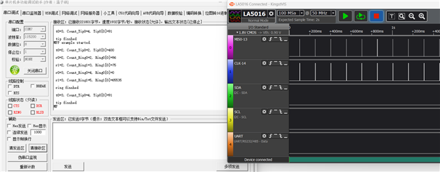
please see my all code, I found if I use PPI for trigger PWM, the PWM can't come in interrupt. I print some information in two PWMs interrupt(RingHandler and TipHandler) by UART, but UART only print PWM0 interrupt information, didn't print PWM1 information, and the wave is wrong, only PWM0 has wave.
But if I didn't use PPI, only use timer interrupt to trigger PWM, everything is ok. please see two pictures
this is using timer picture