Switching GPIO pin between input and output mode

Hi,

Could help me please?

What I need?

1) set GPIO pin as input with internal pulldown and set IRQ for Rising Edge.

In .overlay I add my pin like that:

userpin{
        compatible = "gpio-keys";
        nslpin: nsl_pin{
            gpios = <&gpio0 12 (GPIO_PULL_DOWN | GPIO_ACTIVE_HIGH)>;
			label = "No sleep line";
        };
    };

 Then in code I set pin as INPUT and enabled IRQ

if(gpio_pin_configure_dt(&nslPin, GPIO_INPUT) < 0) while(1);
if(gpio_pin_interrupt_configure_dt(&nslPin, GPIO_INT_EDGE_RISING) != 0) while(1);

2) In code I need sometimes to set this pin as output and set it to logical HIGH (3,3V)

So in code I disabled IRQ on this pin, set it like OUTPUT and set logical HIGH

if(gpio_pin_interrupt_configure_dt(&nslPin, GPIO_INT_DISABLE) != 0) while(1);
if(gpio_pin_configure_dt(&nslPin, GPIO_OUTPUT) < 0) while(1);	
gpio_pin_set_dt(&nslPin,1);

3) Later on I need to set it again as in step 1 (set GPIO pin as input with internal pulldown and set IRQ for Rising Edge.)
Unfortunatelly it does not work I can always see (in the scope) the pin is in logical HIGH - what is wrong with my code?
Thank you for any help. Jan.
Parents
  • Hi,

    Thank you for your patience.

    So basically your query is regarding configuring GPIO pin as input and output.

    As per your provided information, I created a sample project and added the overlay.

    I was able to configure a pin (in my case P0.26) as an input pin, set an interrupt on it, disable the interrupt and configure it as an output port.

    I am attaching my setup (main.c and overlay) here.

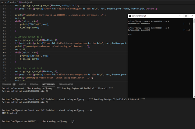
    I can read the status of GPIO pins using nrfjprog command-line tool.

    GPIO0 base address is 0x50000000

    And the offset of DIR (direction either input or output) register of GPIO is 0x514.

    You can see here in the attached image that I am reading once from the DIR register when the pin is configured as INPUT, and the next time when the pin is configured as OUTPUT.

    After checking the values read, you can see that our pin (P0.26) direction bit values are changing from 0 to 1, which means first it was configured as input, and now (at the later stage of code) as output.

    Snapshot attached for clarification:

    Source file: 

    /* Copyright (c) 2016 Open-RnD Sp. z o.o.
     * Copyright (c) 2020 Nordic Semiconductor ASA
     * SPDX-License-Identifier: Apache-2.0 */
    
    #include <zephyr/kernel.h>
    #include <zephyr/device.h>
    #include <zephyr/drivers/gpio.h>
    #include <zephyr/sys/util.h>
    #include <zephyr/sys/printk.h>
    #include <inttypes.h>
    
    //SELECT BUTTON PIN HERE (either line13 or line14)
    //static const struct gpio_dt_spec button  = GPIO_DT_SPEC_GET_OR(DT_ALIAS(sw0), gpios, {0});	        //SW0 as button
    static const struct gpio_dt_spec button = GPIO_DT_SPEC_GET_OR(DT_NODELABEL(nslpin), gpios, {0});        //nslpin as button
    
    static struct gpio_callback button_cb_data;																//cb
    
    void button_pressed(const struct device *dev, struct gpio_callback *cb, uint32_t pins)
    {
    	printk("Button pressed at %" PRIu32 "\n", k_cycle_get_32());
    }
    
    void main(void)
    {
    	int ret; 
    
    	if (!device_is_ready(button.port)) {printk("Error: button device %s is not ready\n",button.port->name);return;}
    
    	//Configure as INPUT	
    	ret = gpio_pin_configure_dt(&button, GPIO_INPUT);
    	if (ret != 0) {printk("Error %d: failed to configure %s pin %d\n", ret, button.port->name, button.pin);return;}
    
    	//Configure Interrupt
    	ret = gpio_pin_interrupt_configure_dt(&button,GPIO_INT_EDGE_TO_ACTIVE);
    	if (ret != 0) {printk("Error %d: failed to configure interrupt on %s pin %d\n",ret, button.port->name, button.pin);return;}
    	gpio_init_callback(&button_cb_data, button_pressed, BIT(button.pin));
    	gpio_add_callback(button.port, &button_cb_data);
    	printk("Set up button at %s pin %d\n", button.port->name, button.pin);
    
    	printk("\n\nButton Configured as Input and INT Enabled... check using nrfjprog ...");
    	ret = 10;
    	while(ret-- != 0){
    		printk("%2d\b\b", ret);
    		k_msleep(1000);
    	}
    
    	//Disable Interrupt
    	ret = gpio_pin_interrupt_configure_dt(&button, GPIO_INT_DISABLE);
    	if (ret != 0) {printk("Error %d: failed to DISABLE interrupt on %s pin %d\n",ret, button.port->name, button.pin);return;}	
    	printk("\nINT Disabled\n");
    
    	//Configure as OUTPUT
    	ret = gpio_pin_configure_dt(&button, GPIO_OUTPUT);
    	if (ret != 0) {printk("Error %d: failed to configure %s pin %d\n", ret, button.port->name, button.pin);return;}	
    	
    	printk("\n\nButton Configured as OUTPUT ... check using nrfjprog ...");
    	ret = 10;
    	while(ret-- != 0){
    		printk("%2d\b\b", ret);
    		k_msleep(1000);
    	}
    
    	//Setting output to 1
    	ret = gpio_pin_set_dt(&button, 1);
    	if (ret != 0) {printk("Error %d: Failed to set output on %s pin %d\n", ret, button.port->name, button.pin);return;}	
    	printk("\n\nOutput value set: Check using multimeter ...");
    	ret = 10;
    	while(ret-- != 0){
    		printk("%2d\b\b", ret);
    		k_msleep(1000);
    	}
    
    	//Setting output to 0
    	ret = gpio_pin_set_dt(&button, 0);
    	if (ret != 0) {printk("Error %d: Failed to set output on %s pin %d\n", ret, button.port->name, button.pin);return;}	
    	printk("\n\nOutput value reset: Check using multimeter ...");
    	ret = 10;
    	while(ret-- != 0){
    		printk("%2d\b\b", ret);
    		k_msleep(1000);
    	}
    }

    Overlay: 3755.nrf52840dk_nrf52840.overlay

    Hope it helps,

    Regards,

    Naeem

Reply
  • Hi,

    Thank you for your patience.

    So basically your query is regarding configuring GPIO pin as input and output.

    As per your provided information, I created a sample project and added the overlay.

    I was able to configure a pin (in my case P0.26) as an input pin, set an interrupt on it, disable the interrupt and configure it as an output port.

    I am attaching my setup (main.c and overlay) here.

    I can read the status of GPIO pins using nrfjprog command-line tool.

    GPIO0 base address is 0x50000000

    And the offset of DIR (direction either input or output) register of GPIO is 0x514.

    You can see here in the attached image that I am reading once from the DIR register when the pin is configured as INPUT, and the next time when the pin is configured as OUTPUT.

    After checking the values read, you can see that our pin (P0.26) direction bit values are changing from 0 to 1, which means first it was configured as input, and now (at the later stage of code) as output.

    Snapshot attached for clarification:

    Source file: 

    /* Copyright (c) 2016 Open-RnD Sp. z o.o.
     * Copyright (c) 2020 Nordic Semiconductor ASA
     * SPDX-License-Identifier: Apache-2.0 */
    
    #include <zephyr/kernel.h>
    #include <zephyr/device.h>
    #include <zephyr/drivers/gpio.h>
    #include <zephyr/sys/util.h>
    #include <zephyr/sys/printk.h>
    #include <inttypes.h>
    
    //SELECT BUTTON PIN HERE (either line13 or line14)
    //static const struct gpio_dt_spec button  = GPIO_DT_SPEC_GET_OR(DT_ALIAS(sw0), gpios, {0});	        //SW0 as button
    static const struct gpio_dt_spec button = GPIO_DT_SPEC_GET_OR(DT_NODELABEL(nslpin), gpios, {0});        //nslpin as button
    
    static struct gpio_callback button_cb_data;																//cb
    
    void button_pressed(const struct device *dev, struct gpio_callback *cb, uint32_t pins)
    {
    	printk("Button pressed at %" PRIu32 "\n", k_cycle_get_32());
    }
    
    void main(void)
    {
    	int ret; 
    
    	if (!device_is_ready(button.port)) {printk("Error: button device %s is not ready\n",button.port->name);return;}
    
    	//Configure as INPUT	
    	ret = gpio_pin_configure_dt(&button, GPIO_INPUT);
    	if (ret != 0) {printk("Error %d: failed to configure %s pin %d\n", ret, button.port->name, button.pin);return;}
    
    	//Configure Interrupt
    	ret = gpio_pin_interrupt_configure_dt(&button,GPIO_INT_EDGE_TO_ACTIVE);
    	if (ret != 0) {printk("Error %d: failed to configure interrupt on %s pin %d\n",ret, button.port->name, button.pin);return;}
    	gpio_init_callback(&button_cb_data, button_pressed, BIT(button.pin));
    	gpio_add_callback(button.port, &button_cb_data);
    	printk("Set up button at %s pin %d\n", button.port->name, button.pin);
    
    	printk("\n\nButton Configured as Input and INT Enabled... check using nrfjprog ...");
    	ret = 10;
    	while(ret-- != 0){
    		printk("%2d\b\b", ret);
    		k_msleep(1000);
    	}
    
    	//Disable Interrupt
    	ret = gpio_pin_interrupt_configure_dt(&button, GPIO_INT_DISABLE);
    	if (ret != 0) {printk("Error %d: failed to DISABLE interrupt on %s pin %d\n",ret, button.port->name, button.pin);return;}	
    	printk("\nINT Disabled\n");
    
    	//Configure as OUTPUT
    	ret = gpio_pin_configure_dt(&button, GPIO_OUTPUT);
    	if (ret != 0) {printk("Error %d: failed to configure %s pin %d\n", ret, button.port->name, button.pin);return;}	
    	
    	printk("\n\nButton Configured as OUTPUT ... check using nrfjprog ...");
    	ret = 10;
    	while(ret-- != 0){
    		printk("%2d\b\b", ret);
    		k_msleep(1000);
    	}
    
    	//Setting output to 1
    	ret = gpio_pin_set_dt(&button, 1);
    	if (ret != 0) {printk("Error %d: Failed to set output on %s pin %d\n", ret, button.port->name, button.pin);return;}	
    	printk("\n\nOutput value set: Check using multimeter ...");
    	ret = 10;
    	while(ret-- != 0){
    		printk("%2d\b\b", ret);
    		k_msleep(1000);
    	}
    
    	//Setting output to 0
    	ret = gpio_pin_set_dt(&button, 0);
    	if (ret != 0) {printk("Error %d: Failed to set output on %s pin %d\n", ret, button.port->name, button.pin);return;}	
    	printk("\n\nOutput value reset: Check using multimeter ...");
    	ret = 10;
    	while(ret-- != 0){
    		printk("%2d\b\b", ret);
    		k_msleep(1000);
    	}
    }

    Overlay: 3755.nrf52840dk_nrf52840.overlay

    Hope it helps,

    Regards,

    Naeem

Children
Related